


Reelmaster 3550−D Hydraulic SystemPage 4 − 113
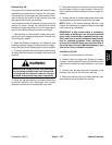
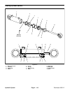
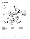
Removal (Fig. 71)
1. Park machine on a level surface. Lower cutting units,
stop engine and engage parking brake. Remove key
from the ignition switch.
2. Thoroughly clean hydraulic hose ends and fittings on
steering control valve to prevent hydraulic system con-
tamination.
WARNING
Before disconnecting or performing any work on
the hydraulic system, all pressure in the system
must be relieved. See Relieving Hydraulic Sys
-
tem Pressure in the General Information section
of this chapter.
3. Label all hydraulic hoses and fittings for assembly
purposes. Note port identification on steering control
valve.
4. Remove steering control valve from the steering
column.
Installation (Fig. 71)
1. Install steering control valve to the steering column.
Use labels placed during the removal process to proper-
ly install hydraulic hoses to control valve.
2. Adjust location of steering shield so that it just con-
tacts hydraulic hoses when the steering wheel is tilted
to its lowest position.
3. Make sure hydraulic tank is full. Add correct oil if ne-
cessary.
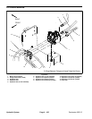
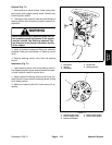
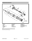
1. Tilt bracket
2. Jam nut
3. Flat washer
4. Friction disc
5. Steering tilt lever
Figure 72
3
1
4
5
2
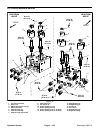
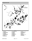
Figure 73
5
1
3
2
4
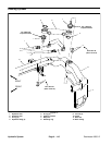
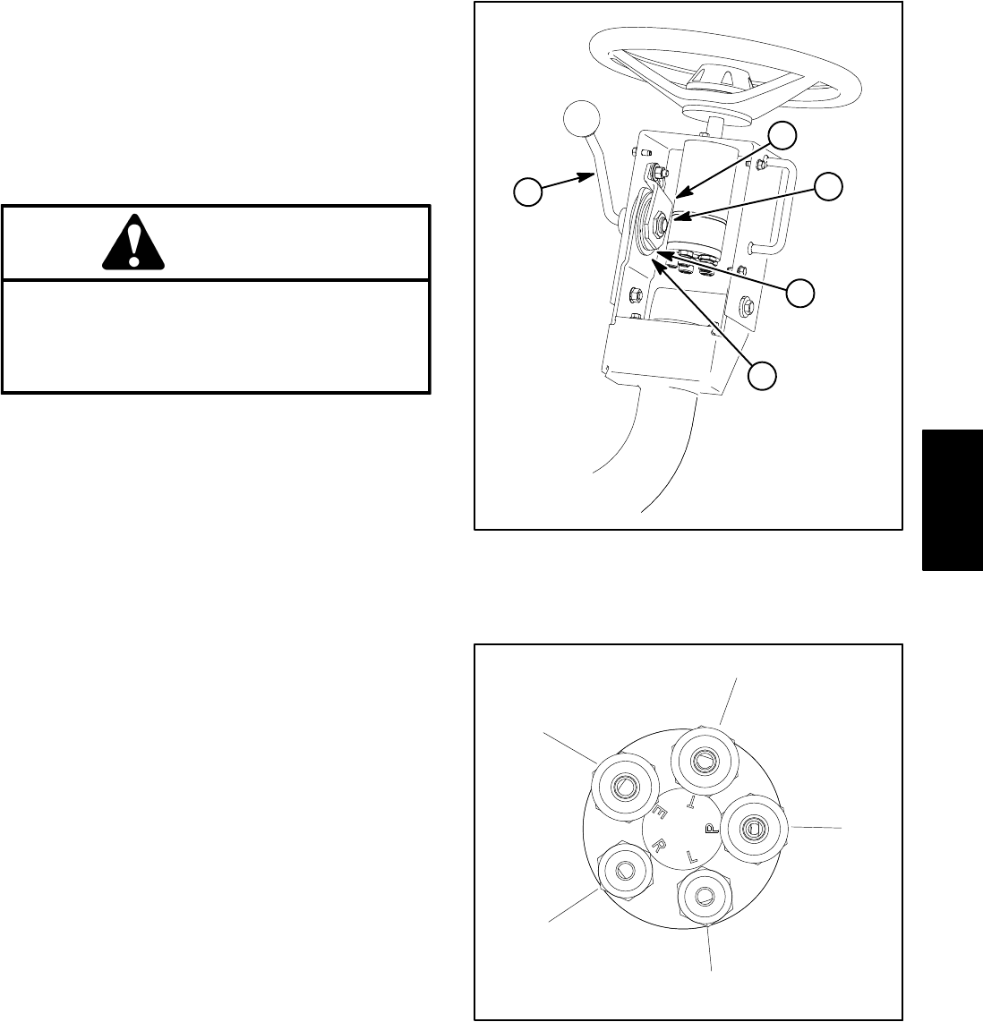
1. Hose from gear pump
2. Hose to charge circuit
3. Hose to lift manifold
4. Hose to steer cylinder
5. Hose to steer cylinder
Hydraulic
System