


Reelmaster 3550−DGroomer Page 8 − 12
Groomer Reel Service
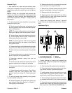
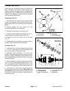
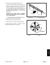
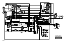
Inspect groomer reel blades frequently for damage and
wear. Straighten bent blades. Either replace worn
blades or reverse the blades to put the sharpest blade
edge forward (Fig. 9). Blades that are rounded to the
midpoint of the blade tip must be reversed or replaced
for best groomer performance.
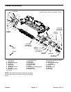
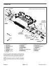
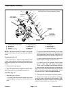
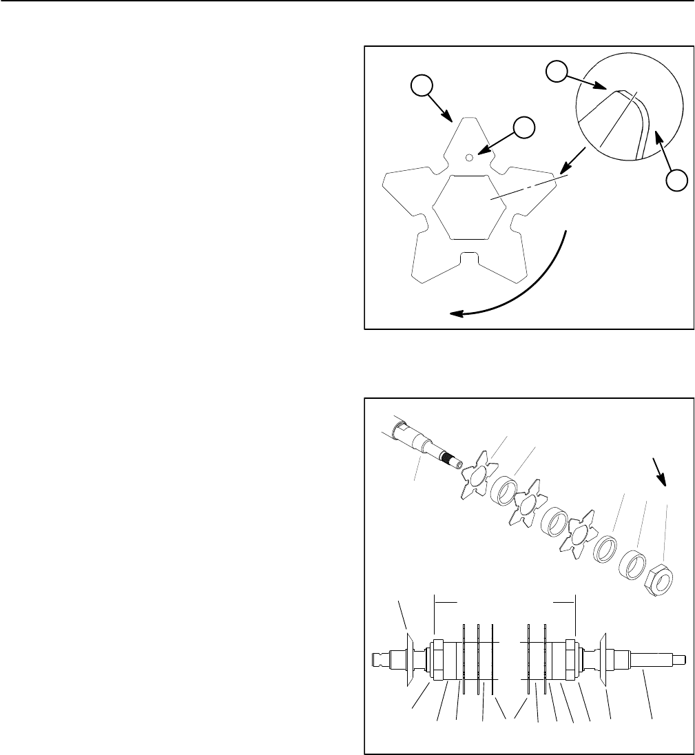
Disassembly (Fig. 10)
1. Park machine on a clean and level surface, lower
cutting units completely to the ground, stop engine, en-
gage parking brake and remove key from the ignition
switch.
2. Remove groomer reel from cutting unit (see
Groomer Reel Removal in this section).
3. Remove excluder seals from groomer reel.
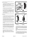
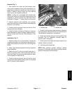
4. If groomer reel is equipped with broomer kit (Fig. 11),
remove straps and broomer brushes from reel.
5. Remove lock nut from either end of the shaft
(Fig. 10).
6. Remove spacers and blades from groomer shaft. If
needed, remove second lock nut from shaft.
Assembly (Fig. 10)
1. Install lock nut on drive end of groomer shaft. Place
a 1-1/4” (31.7 mm) spacer, a1/4” (6.3 mm) spacer, and
then the first blade on the groomer shaft.
2. Alternately install remaining 1−1/4” (31.7 mm)
spacers and blades making sure that all blades are sep-
arated by a spacer. Additionally, rotate location hole on
each installed blade one flat of the shaft, in a counter-
clockwise direction.
3. When all blades have been installed, place remain-
ing 1/4” (6.3 mm) spacer against blade then final 1−1/4”
(31.7
mm) spacer on shaft. Thread second lock nut onto
the shaft. Center blades on shaft by adjusting lock nuts.
4. Using wrench on shaft flats to prevent shaft from
turning, torque second lock nut from 200 to 250 in−lb
(23 to 28 N−m). After torquing lock nut, spacers should
not be free to rotate and groomer blades should be
centered on shaft.
1. Groomer blade
2. Location hole
3. Sharp edge
4. Dull (rounded) edge
Figure 9
ROTATION
GROOMER
3
4
2
1
MIDPOINT
1. Groomer reel shaft
2. Groomer blade (32)
3. 1−1/4” (31.7 mm) Spacer
(33)
4. 1/4” (6.3 mm) Spacer (2
)
5. Lock nut (2)
6. Excluder seal
Figure 10
1
2
3
4
200 to 250 in−lb
(23 to 28 N−m)
5
3
CENTERED ON SHAFT
1 235
5
6
6
43 3 43