


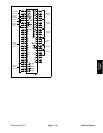
Reelmaster 3550−D Page 5 − 21 Electrical System
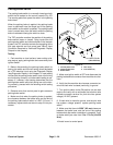
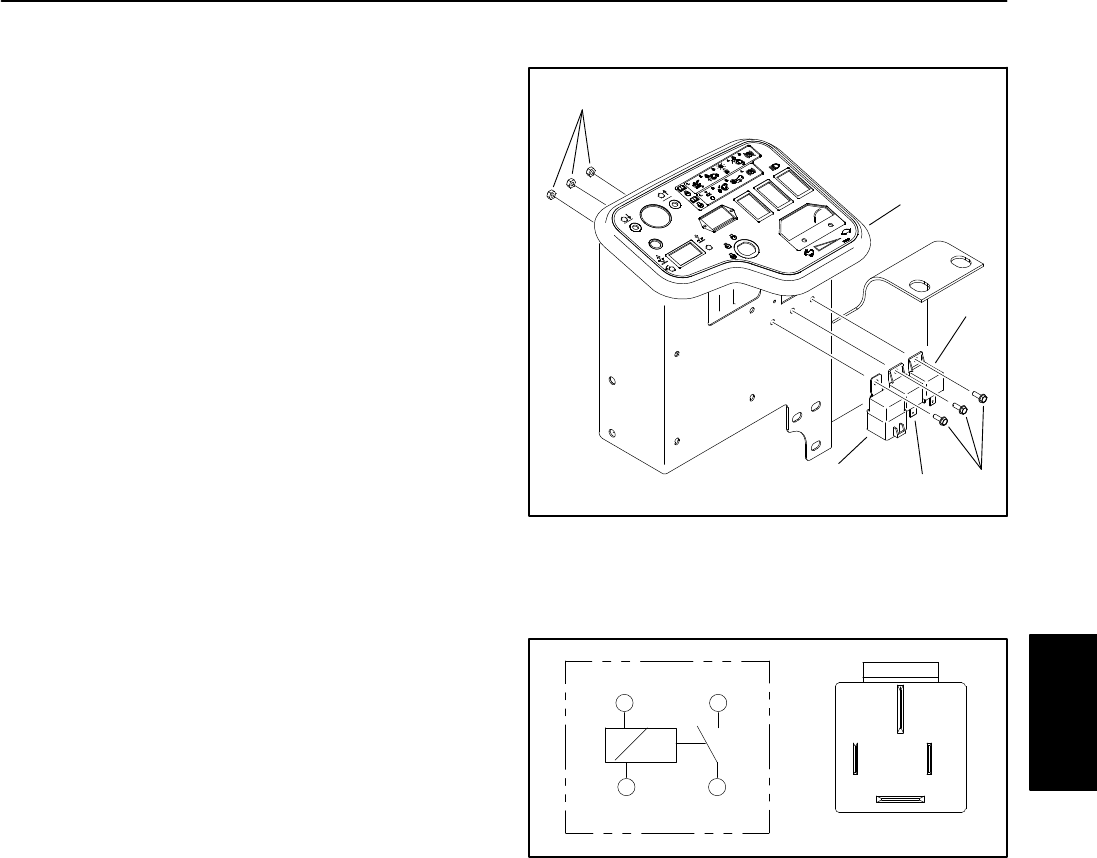
Main Power Relay
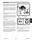
The main power relay is secured to the control panel as-
sembly next to the operator seat (Fig. 15). This relay is
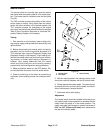
attached to the wire harness with a four (4) wire connec-
tor (Fig. 16). The relay can be accessed by removing the
control panel cover.
The main power relay is used to provide current to the
TEC controller and most of the fuse protected circuits
(worklights, power point, console indicators and other
electric equipment). When the ignition switch is in the
RUN or START position, the main power relay is ener-
gized.
Testing
1. Park machine on a level surface, lower cutting units,
stop engine, engage parking brake and remove key
from the ignition switch.
2. To make sure that machine operation does not occur
unexpectedly, disconnect negative (−) cable from bat-
tery and then disconnect positive (+) cable from battery
(see Battery Service in the Service and Repairs section
of this chapter).
3. Remove cover from control panel and locate main
power relay (Fig. 15).
4. Disconnect wire harness connector from relay. Re-
move relay from mounting bracket for testing.
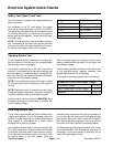
NOTE: Prior to taking small resistance readings with a
digital multimeter, short the meter test leads together.
The meter will display a small resistance value (usually
0.5 ohms or less). This resistance is due to the internal
resistance of the meter and test leads. Subtract this val-
ue from from the measured value of the component you
are testing.
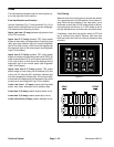
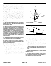
5. Using a multimeter, verify that coil resistance be-
tween terminals 86 and 85 is approximately 72 ohms.
6. Connect multimeter (ohms setting) leads to relay ter-
minals 30 and 87. Ground terminal 86 and apply +12
VDC to terminal 85. The relay should make and break
continuity between terminals 30 and 87 as +12 VDC is
applied and removed from terminal 85.
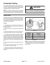
1. Lock nut
2. Start relay
3. Main power relay
4. Glow relay
5. Screw
6. Mounting bracket
Figure 15
2
3
4
1
5
6
Figure 16
86 87
85 30
85 86
87
30
7. Disconnect voltage and test leads from the relay ter-
minals.
8. After testing is completed, secure relay to mounting
bracket and connect wire harness connector to relay.
Install cover to control panel.
9. Connect positive (+) cable to battery and then con-
nect negative (−) cable to battery (see Battery Service
in the Service and Repairs section of this chapter).
Electrical
System