


Reelmaster 3550−D Hydraulic SystemPage 4 − 47
Cutting Unit Circuit Testing − Reel Motor Efficiency/
Case Drain Test
The reel motor efficiency/case drain test is the second
in a series of tests recommended to check cutting unit
circuit performance. Over a period of time, a reel motor
can wear internally. This test measures case drain
volume while restricting flow across the motor ports.
Case drain volume under load of more than 9% of total
motor flow indicates the gears and wear plates in the
motor have worn. A worn motor may by−pass hydraulic
fluid to its case drain causing the motor to be less effi-
cient. Eventually, enough fluid loss will cause the reel
motor to stall under heavy cutting conditions. Continued
operation with a worn, inefficient motor can generate ex-
cessive heat, cause damage to seals and other com-
ponents in the hydraulic system, and affect quality of cut.
NOTE: One method to find a failing or malfunctioning
cutting unit motor is to have another person observe the
machine while mowing in dense turf. A bad motor will run
slower, produce fewer clippings and may cause a differ-
ent appearance on the turf.
Special Equipment Required:
S Flow Meter with Pressure Gauge that has at least
a 12 GPM (45 LPM) capacity.
S Phototach (non−contact tachometer).
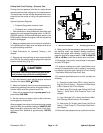
1. Make sure hydraulic fluid is at normal operating tem-
perature by operating the machine for approximately 10
minutes. Make sure the hydraulic tank is full.
2. Park the machine on a level surface with the cutting
units lowered and the reel enable/disable switch in the
disable position. Make sure engine is off and the parking
brake is disengaged.
3. Read Precautions for Hydraulic Testing in this
chapter.
4. Make sure that traction pedal is adjusted to the neut-
ral position.
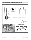
NOTE: The cutting unit motors are connected in series.
If a faulty reel motor is not obvious (based on quality of
cut issues) you may have to test all the reel motors in the
circuit. If testing all reel motors, start with the first motor
in the series (#4 cutting unit).
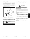
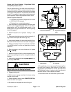
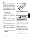
5. Hydraulic oil passes through each reel motor from
the front to the rear. Disconnect the return hose from the
motor (hose at the rear of the reel motor).
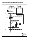
6. Install hydraulic tester between the motor and the
disconnected return hose. Make sure the tester flow
control valve is fully open.
7. Make sure backlap knob on the hydraulic manifold is
in the MOW position and reel speed is set to maximum.
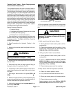
8. Disconnect hose from reel motor case drain at the
hydraulic tube (#1 cutting unit), or from the bulkhead fit-
ting (#2, 3, 4, & 5 cutting units). Cap the hydraulic tube
or bulkhead fitting to prevent system contamination.
9. Place open end of disconnected case drain hose into
a drain pan.
10.Two people are required to complete the following
steps. One person should sit in the operator’s seat and
operate the machine while another person reads the
tester and measures reel motor case drain volume.
11.Start the engine, and move throttle to full speed
(3220 +
50 RPM).
12.Verify with a phototach that the pump speed is ap-
proximately 3090 RPM.
CAUTION
Keep away from reels during test to prevent per-
sonal injury from the rotating reel blades.
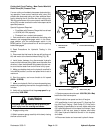
13.Engage cutting units and slowly close tester flow
control valve until 1200 PSI (82.7 Bar) is obtained.
14.Hold disconnected motor case drain hose into a con-
tainer graduated in ounces or milliliters (e.g. Toro
#TOR4077) and collect hydraulic fluid for 30 seconds.
After 30 seconds, remove hose end from container.
15.Record amount of fluid collected in the container.
16.Disengage cutting units, set throttle to low speed,
and stop engine.
17.If volume is more than 43 oz (1265 milliliters), repair
or replace the tested reel motor.
18.Remove tester and reconnect hydraulic hoses.
19.Check hydraulic fluid level (see Traction Unit Operat-
or’s Manual).
20.Repeat test for remaining reel motors as needed.
Hydraulic
System