


Reelmaster 3550−D
Cutting Units
Page 7 − 29
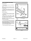
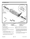
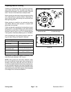
Assembly of Cutting Reel (Fig. 35)
1. If flocked seals and/or bearings were removed from
reel shaft, discard removed components and replace.
2. Make sure that the retaining ring is fully seated into
the groove on the cutting reel shaft.
3. Install special washer with recessed slots toward
bearing. Drive special washer onto reel shaft until it
squarely contacts retaining ring.
4. Slide flocked seal and bearing onto reel shaft with
flocked side of seal against bearing.
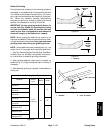
5. Install threaded insert.
A. One insert has LH threads and the other insert
has RH threads. The insert with LH threads has a
groove on the insert face. A groove is cut 2.2” (5.6
cm) from the end of the reel shaft to identify the reel
end that has LH threads.
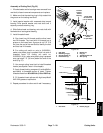
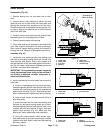
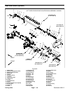
B. For cutting unit serial no. prior to 315000001,
make sure plastic plug is pressed flush into end of
threaded insert. For cutting unit serial no.
315000001 & Up, make sure plastic plug is pressed
unto reel shaft 1.5” (38 mm) below the end of the
shaft (Fig. 37).
C. Use correct spline insert tool to install threaded
inserts (see Special Tools in this chapter).
D. Apply thread locking compound (Loctite #242 or
equivalent) to threaded portion of insert. Tighten
threaded insert from 85 to 95 ft-lb (115 to 128 N−m).
E. Fill threaded insert splines with high temp Mobil
XHP−222 grease or equivalent.
6. Repeat procedure for other end of reel if necessary.
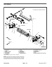
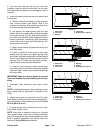
1. Side plate
2. Retaining ring (2)
3. Special washer (2)
4. Flocked seal (2)
5. Bearing (2)
6. Plug (2)
7. Threaded insert LH
8. Wire spring
Figure 36
Loctite #242
85 to 95 ft−lb
(115 to 129 N−m)
Mobil XHP−222
Grease
Flocked
Surface
2
3
4
5
6
7
Toward
Bearing
1
8
or equivalent
1. Reel shaft 2. Plastic plug (2)
Figure 37
1.5” (38 mm)
DPA Cutting
Units