


Reelmaster 3550−D
Cutting Units
Page 7 − 38
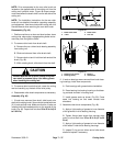
E. Apply antiseize lubricant to splines of roller brush
shaft before sliding hardened washer(s) and driven
pulley onto shaft. Torque flange nut that secures driv-
en pulley to roller brush shaft from 27 to 33 ft−lb (36
to 45 N−m).
F. Position excluder seals on brush shaft so that
seals just touch bearing housings.
CAUTION
Contact with the reel or other cutting unit parts
can result in personal injury. Use heavy gloves
when handling the cutting reel.
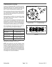
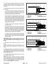
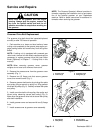
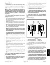
G. To install drive belt, loop belt around driven pulley
and over the top of the idler pulley. While rotating the
cutting reel, carefully guide belt onto drive pulley
(Fig. 51). After belt installation, make sure that belt
and pulley grooves are aligned and that belt is cen-
tered in idler pulley.
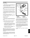
4. Check alignment of pulleys with a straight edge
placed along the outer face of the driven pulley (Fig. 52).
The outer faces of the driven and drive pulleys (not the
idler pulley) should be in line within 0.030” (0.76 mm).
If necessary to align pulleys, remove driven pulley from
brush shaft and add or remove hardened washer(s) until
drive and driven pulleys are aligned within 0.030” (0.76
mm).
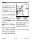
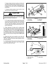
5. Check that roller brush is parallel to rear roller with
0.060” (1.5 mm) clearance to light contact with roller
(Fig. 53). If contact is incorrect, brush operation will be
adversely affected.
6. Lubricate grease fittings on brush bearing housings
until grease purges past inboard seals. Wipe excess
grease from seals and fittings.
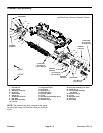
1. Drive pulley
2. Driven pulley
3. Idler pulley
4. Drive belt
Figure 51
2
3
1
4
1. Drive pulley
2. Driven pulley
3. Straight edge
Figure 52
1
2
3
CHECK
ALIGNMENT
1. Rear roller brush
2. Rear roller
3. Light contact
Figure 53
2
1
3