


Reelmaster 3550−D GroomerPage 8 − 7
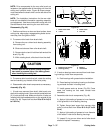
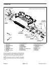
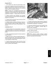
Removal (Fig. 3)
1. Park machine on a clean and level surface, lower
cutting units completely to the ground, stop engine, en-
gage parking brake and remove key from the ignition
switch.
NOTE: If cutting unit is equipped with powered rear
roller brush, removal of roller brush components will be
necessary to service groomer plate assemblies (see
Roller Brush (Optional) in Chapter 7 − Cutting Units in
this manual).
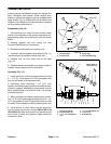
2. To remove groomer plate assembly from groomer
drive side of cutting unit:
A. Remove groomer belt cover and groomer drive
belt from groomer drive (see Groomer Belt Replace-
ment in this section).
NOTE: To prevent cutting reel from turning when re-
moving drive pulley, block reel with piece of wood.
B. Remove flange head screw that retains drive pul-
ley. Pull drive pulley from drive shaft. Locate and re-
trieve square key from drive shaft.
NOTE: To prevent groomer shaft from turning when
removing driven pulley, use wrench on shaft flats to
hold groomer shaft.
C. Remove the flange nut that secures driven pulley
to groomer shaft. Remove driven pulley from shaft.
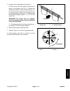
D. Slide washer(s) and pulley spacer from groomer
shaft.
E. Remove shoulder bolt and spacer that secures
quick−up ball joint rod to groomer plate.
F. Disconnect extension spring from stud on
groomer plate.
G. Remove two (2) socket head screws that secure
groomer components to cutting unit side plate.
H. Remove pivot hub and idler plate assembly from
cutting unit.
I. Support groomer shaft to prevent it from falling.
Carefully slide drive side groomer plate from
groomer shaft and cutting unit. Remove groomer
shim.
3. To remove groomer plate assembly from groomer
non−drive side of cutting unit:
A. Remove hydraulic reel motor from cutting unit
(see Hydraulic Reel Motor Removal in Chapter 7 −
Cutting Units in this manual).
B. Remove shoulder bolt and spacer that secures
quick−up ball joint rod to groomer plate.
C. Remove two (2) socket head screws that secure
groomer components to cutting unit side plate.
D. Remove pivot hub from cutting unit.
E. Support groomer shaft to prevent it from falling.
Carefully slide non−drive side groomer plate from
groomer shaft and cutting unit.
4. Inspect seals, bearings and bushing in groomer
plates. Remove and discard damaged or worn compon-
ents.
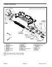
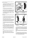
Installation (Fig. 3)
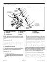
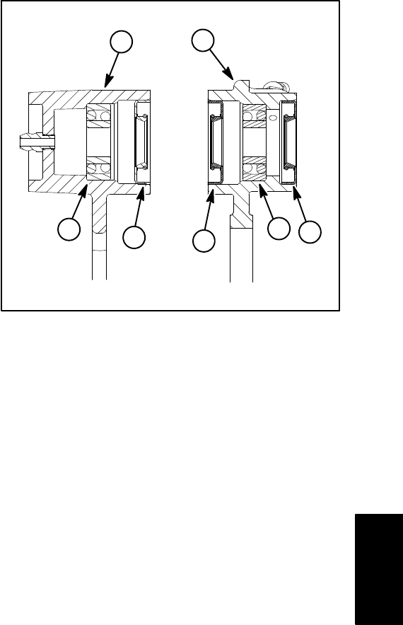
1. Drive side groomer plate
2. Non−drive groomer plate
3. Bearing
4. Grease seal
Figure 4
2
1
4
3
4
3
4
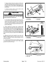
1. If seals, bearings or bushing was removed from
groomer plates, install new components noting proper
orientation (Fig. 4).
A. Pack bearings with grease before installation.
B. Press bearings into groomer plate so that bear-
ings contact shoulder in groomer plate bore.
C. Install grease seals so that seal lips are posi-
tioned toward the groomer blade location. Seals
should be flush with surface of groomer plate.
D. Press bushings into groomer plate until the bush-
ing contacts the shoulder in the groomer plate bore.
E. If groomer studs (not shown) were removed from
groomer plate, install new studs into groomer plate
and torque from 14 to 18 ft−lb (19 to 24 N−m).
Groomer