


Reelmaster 3550−DHydraulic System Page 4 − 98
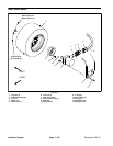
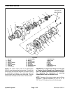
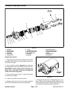
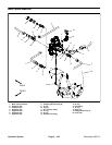
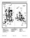
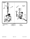
Assembly (Fig. 61)
1. Lubricate O–rings, pressure seals, back−up gaskets
and wear plate grooves with a thin coat of petroleum jel-
ly. Lubricate all other internal parts freely with clean hy-
draulic fluid.
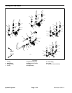
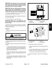
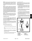
2. Install new seals into front flange (Fig. 63):
A. Press new shaft seal into front flange until it
reaches the bottom of the bore.
B. Install backup washer into front flange and then
install retaining ring into the groove of the front
flange.
C. Install new dust seal into front flange.
3. Place front flange, seal side down, on a flat surface.
4. Install the outer pressure seal, flat side outward, into
the grooves in the outer wear plate. Follow by carefully
placing the outer backup gasket, flat side outward, be-
tween the pressure seal and the grooves in the outer
wear plate.
5. Apply a light coating of petroleum jelly to the exposed
side of the front flange.
6. Lubricate the drive gear shaft with clean hydraulic
fluid. Insert the drive end of the drive shaft through the
outer wear plate with the pressure seal side down and
the open side of the pressure seal pointing to the inlet
side of the motor. Carefully install shaft into front flange.
7. Lubricate the idler gear shaft with clean hydraulic flu-
id. Install idler gear shaft into the remaining position in
the outer wear plate with gear teeth in the mated position
noted during dis−assembly. Apply a light coating of
clean hydraulic fluid to gear faces.
8. Install the inner pressure seal, flat side outward, into
the grooves in the inner wear plate. Follow by carefully
placing the inner backup gasket, flat side outward, be-
tween the pressure seal and the grooves in the inner
wear plate.
9. Install inner wear plate with pressure seal side up
and open side of the pressure seal pointing to the inlet
side of the motor.
10.Apply a light coating of petroleum jelly to new O–ring
and O–ring grooves in the body. Install new O–ring to the
body.
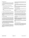
NOTE: When assembling the motor, check the marker
line on each part to make sure the parts are properly
aligned during assembly.
11.Install locating dowels in body. Align marker line on
the body and front flange.
IMPORTANT: Do not dislodge seals during installa-
tion.
12.Gently slide the body onto the assembly. Firm hand
pressure should be sufficient to engage the dowels.
13.Check to make sure that the surface of the body con-
tacts the front flange. If the body does not contact the
front flange, check assembly for a shifted pressure seal,
backup gasket or O–ring. Correct before proceeding.
14.Install the four (4) cap screws with washers and hand
tighten screws.
IMPORTANT: Prevent damage when clamping the
motor into a vise; use a vise with soft jaws and
clamp on the front flange only.
15.Place front flange of the motor into a vise with soft
jaws and alternately torque the cap screws 18 ft−lb (25
N−m).
16.Remove motor from vise.
17.Place a small amount of clean hydraulic fluid in the
inlet of the motor and rotate the drive shaft away from the
inlet one revolution. If any binding is noted, disassemble
the motor and check for assembly problems.