


Reelmaster 3550−DPage 5 − 24Electrical System
Toro Electronic Controller (TEC)
The Reelmaster 3550−D uses a Toro Electronic Control-
ler (TEC) to monitor the condition of various switches
(inputs) and directs power to a variety or outputs to con-
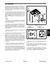
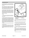
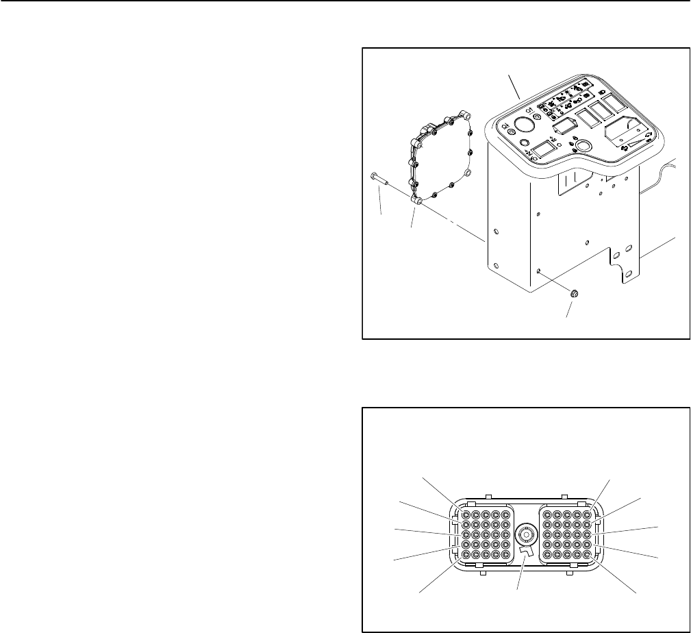
trol certain machine functions. The controller is located
under the control panel (Fig. 22). The handheld Diag-
nostic Display with the correct overlay should be used
to check inputs and outputs of the controller (see Dia-
gnostic Display in this chapter).
Logic power is provided to the controller as long as the
battery cables are connected to a charged battery. A two
(2) amp fuse (upper, rear fuse 1) provides circuit protec-
tion for the logic power to the controller.
The TEC controller monitors the states of the following
components as inputs: ignition switch, parking brake
switch, neutral switch, reel lower/raise joystick switches,
reel enable/disable switch, mow/transport switch, seat
switch, backlap switch, engine temperature sender.
Current output to the indicator lights, mow circuit hy-
draulic solenoid valve coil, lift circuit hydraulic solenoid
valve coils and engine components (glow plug relay,
start relay, fuel pump and fuel stop solenoid) are con-
trolled based on the inputs received by the controller.
Circuit protection for the TEC outputs is provided by
three (3) 7.5 Amp fuses (upper, rear fuse 2, 3 and 4).
The machine electrical schematic and wire harness
drawings in Chapter 10 − Foldout Drawings can be used
to identify possible circuit problems between the control-
lers and the input or output devices (e.g. switches and
solenoid coils).
Because of the solid state circuitry built into the control-
ler, there is no method to test the controller directly. The
controller may be damaged if an attempt is made to test
it with an electrical test device, such as a digital multi-
meter.
Electrical power for the controller outputs is provided
through three (3) connectors (PWR2, PWR3 and
PWR4) each protected with a 7.5 amp fuse. A fifty (50)
pin wire harness connector attaches to the controller.
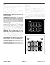
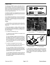
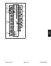
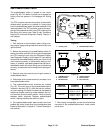
The layout of the wire harness connector that plugs into
the TEC controller is provided (Fig. 23). The TEC con-
troller connection terminal functions and the connector
pins are shown for reference (Fig. 24).
IMPORTANT: When testing for wire harness con-
tinuity at the connector for the TEC controller, take
care to not damage the connector pins with multi-
meter test leads. If connector pins are enlarged or
damaged during testing, connector repair will be
necessary for proper machine operation.
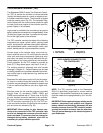
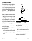
Figure 22
1. Control panel
2. TEC controller
3. Cap screw (4)
4. Flange nut (4)
1
3
2
4
Figure 23
WIRE HARNESS CONNECTOR FOR
TEC CONTROLLER
11
1
21
31
41
10
50
40
30
20
POSITION
NOTE TAB
NOTE: The TEC controller used on the Reelmaster
3550−D is specifically programed for correct machine
operation. If the controller is replaced for any reason, the
controller needs to be reprogrammed by your Toro Dis-
tributor.
IMPORTANT: Before performing any welding on the
machine, disconnect both positive and negative
battery cables from the battery, disconnect the wire
harness connector from the TEC controller and dis-
connect the terminal connector from the alternator.
This will prevent damage to the electrical system of
your Reelmaster.