


Reelmaster 3550−D Page 5 − 35 Electrical System
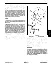
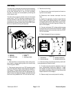
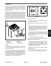
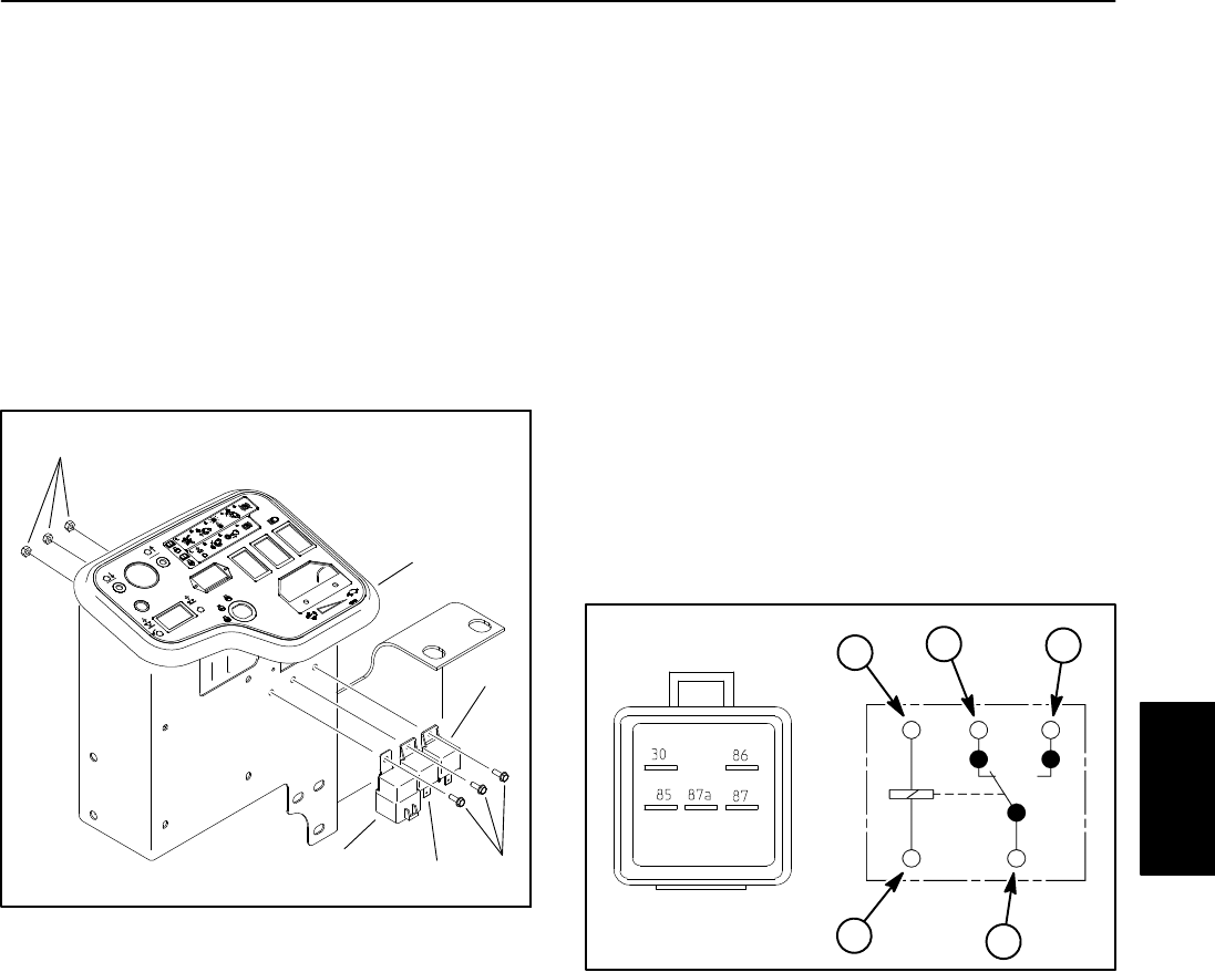
Start Relay
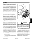
The start relay is secured to the control panel assembly
next to the operator seat (Fig. 37). This relay is attached
to the wire harness with a five (5) wire connector
(Fig. 38). The relay can be accessed by removing the
control panel cover.
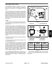
The start relay is used to provide current to the engine
starter motor. The TEC controller energizes and moni-
tors the operation of the start relay when specific input
conditions are met. The start relay should remain ener-
gized while the ignition switch is set to the START posi-
tion for a maximum of thirty (30) seconds.
1. Lock nut
2. Start relay
3. Main power relay
4. Glow relay
5. Screw
6. Mounting bracket
Figure 37
2
3
4
1
5
6
Testing
1. Park machine on a level surface, lower cutting units,
stop engine, engage parking brake and remove key
from the ignition switch.
2. Test the start relay circuit as a TEC electrical output
using the Diagnostic Display (see Diagnostic Display in
this chapter). If output testing verifies that the TEC is en-
ergizing the start relay circuit under the appropriate con-
ditions, leave the diagnostic display connected and test
the circuit wiring between the TEC and the start relay.
3. Test the circuit wiring:
A. Remove cover from control panel and locate re-
lay that is to be tested.
B. Disconnect wire harness connector from the
relay.
C. Position the necessary input(s) to illuminate the
START output LED indicating that the TEC controller
is energizing that function (see Table 3: Input Condi-
tions Required to Illuminate Diagnostic Display Out-
puts in this chapter).
D. Connect multimeter (DC voltage setting) across
the terminals of the wire harness connector. 12VDC
should be present at the connector when the START
LED is illuminated.
E. Repair damaged wiring as necessary.
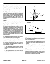
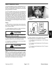
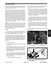
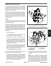
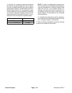
Figure 38
86
85
87A 87
30
2
1
3
4
1. Coil terminal
2. Common terminal
3. Normally closed term.
4. Normally open termina
l
1
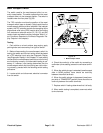
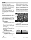
4. If the circuit wiring is functioning correctly, use the fol-
lowing procedure to test the relay.
A. To make sure that machine operation does not
occur unexpectedly, disconnect negative (−) cable
from battery and then disconnect positive (+) cable
from battery (see Battery Service in the Service and
Repairs section of this chapter).
B. Remove relay from control panel for testing.
Electrical
System