


Reelmaster 3550−D Page 5 − 27 Electrical System
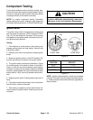
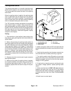
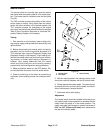
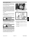
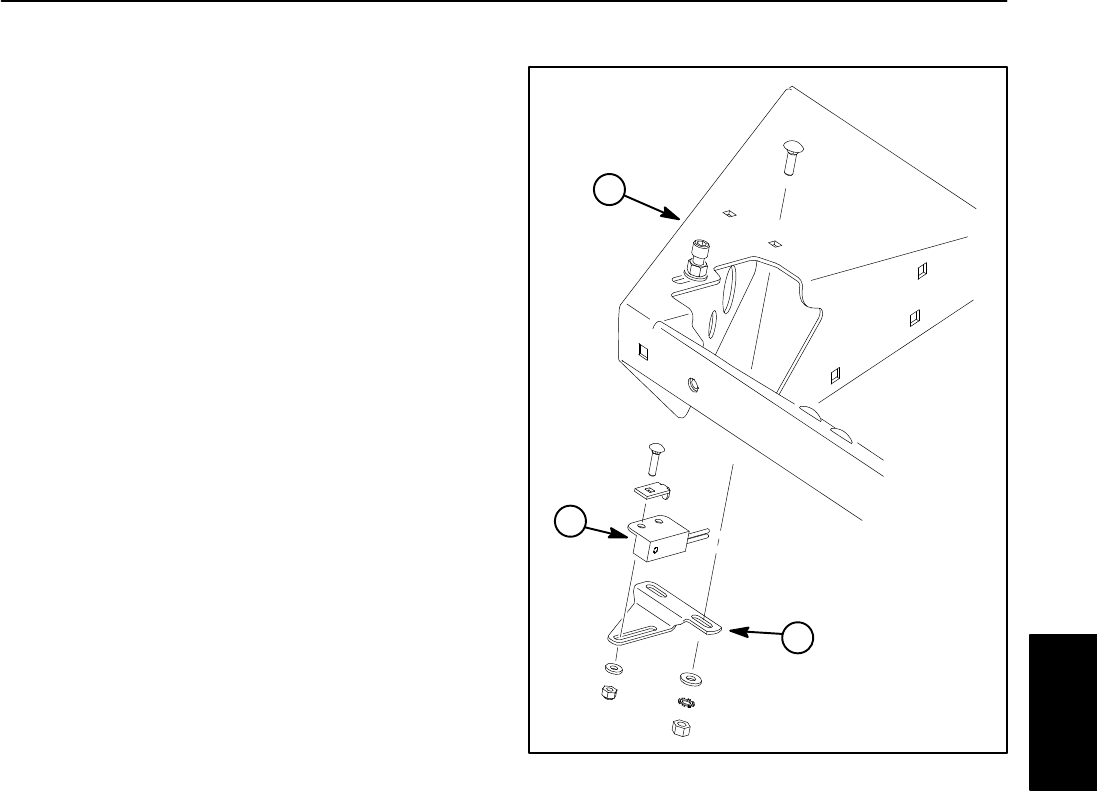
Neutral Switch
The neutral switch is a normally open proximity switch
that closes when the traction pedal is in the neutral posi-
tion. The neutral switch is located under the floor plate
(Fig. 26).
The TEC controller monitors the position of the neutral
switch (open or closed). Using inputs from the neutral
switch and other switches in the interlock system, the
TEC controller controls the energizing of the engine
start relay, and the fuel stop solenoid and fuel pump (see
Table 3: Input Conditions Required to Illuminate Dia-
gnostic Display Outputs in this chapter).
Testing
1. Park machine on level surface, lower cutting units,
stop engine, apply parking brake and remove key from
ignition switch.
2. Before disconnecting the neutral switch for testing,
the switch and its circuit wiring should be tested as a
TEC electrical input using the Diagnostic Display (see
Diagnostic Display in this chapter). If input testing veri-
fies that the neutral switch and circuit wiring are function-
ing correctly, no further switch testing is necessary. If,
however, input testing determines that the neutral
switch and circuit wiring are not functioning correctly,
proceed with the following switch testing procedure.
3. Make sure ignition switch is in the OFF position. Dis-
connect electrical connector from the neutral switch.
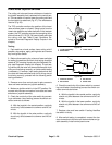
4. Check the continuity of the switch by connecting a
multimeter (ohms setting) across the connector termi-
nals.
1. Neutral switch
2. Floor plate
3. Switch bracket
Figure 26
2
1
3
5. With the traction pedal in the neutral position, there
should be continuity between the two (2) switch leads.
6. Slowly depress the traction pedal. The continuity tes-
ter should show no continuity as the pedal is moved in
either the forward or reverse direction.
7. Reconnect switch after testing.
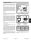
Adjustment
The neutral switch should be installed so that the pin on
the traction pedal (neutral position) is centered with the
switch when the pedal is in the neutral position. The
switch must open with forward or reverse movement of
0.25” to 1.00” (6.3mm to 25.4mm) when measured at
the top of the traction pedal.
Electrical
System