


Reelmaster 3550−D
Cutting Units
Page 7 − 21
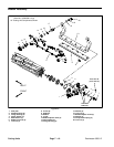
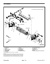
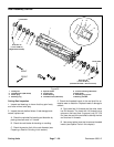
Removal (Fig. 25)
1. Remove lock nut, compression spring and washer
from bedbar adjuster screw.
2. Remove bedbar (see Bedbar Removal in this
chapter.
NOTE: Bedbar adjuster shaft has left−hand internal
threads.
3. Unscrew bedbar adjuster screw from the bedbar ad-
juster shaft.
4. Remove lock nut and flat washer from adjuster shaft.
Slide adjuster shaft and wave washer from cutting unit
frame.
5. Inspect flange bushings in cutting unit frame and re-
move if necessary.
6. If detent is damaged, remove it from cutting unit side
plate by removing the cap screw.
Installation (Fig. 25)
1. If detent was removed, apply Loctite #242 (or equiv-
alent) to threads of cap screw and secure detent to cut-
ting unit side plate with cap screw. Torque cap screw
from 14 to 16 ft−lb (19 to 21 N−m).
2. If flange bushings were removed, apply antiseize lu-
bricant to bore of cutting unit frame. Align key on bushing
to slot in frame and install bushings into frame.
3. Slide wave washer onto adjuster shaft and then slide
adjuster shaft into flange bushings in cutting unit frame.
Secure adjuster shaft with flat washer and lock nut.
Tighten lock nut to shoulder of adjuster shaft and then
torque lock nut from 15 to 20 ft−lb (21 to 27 N−m).
NOTE: Bedbar adjuster shaft has left−hand internal
threads.
4. Apply antiseize lubricant to threads of bedbar adjust-
er screw that fit into adjuster shaft. Thread bedbar ad-
juster screw into adjuster shaft.
5. Install bedbar (see Bedbar Installation in this
chapter).
6. Install washer, compression spring and lock nut onto
adjuster screw. Tighten the lock nut on each bedbar ad-
juster assembly until the compression spring is fully
compressed, then loosen lock nut 1/2 turn.
7. Adjust cutting unit (see Cutting Unit Operator’s
Manual).
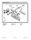
DPA Cutting
Units