


Reelmaster 3550−D Hydraulic SystemPage 4 − 107
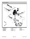
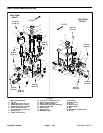
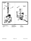
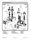
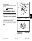
Removal (Fig. 69)
The ports on the lift control manifold are marked for easy
identification of components. Example: S1 is the sole-
noid valve and P is the supply port (see Hydraulic Sche-
matic to identify the function of the hydraulic lines and
cartridge valves at each port location).
The lift control manifold is located on the right side of the
traction unit frame. Access the manifold from above
through the hinged floor plate in front of the operator’s
seat, or from behind (below the traction unit frame).
1. Park machine on a level surface. Lower cutting units,
stop engine and engage parking brake. Remove key
from the ignition switch.
2. Read the General Precautions for Removing and
Installing Hydraulic System Components at the begin-
ning of the Service and Repairs section of this chapter.
3. To prevent contamination of hydraulic system during
lift control manifold removal, thoroughly clean exterior of
manifold.
WARNING
Make sure that cutting units are fully lowered be-
fore loosening hydraulic lines from lift manifold.
If cutting units are raised as hydraulic lines are
loosened, cutting units may drop unexpectedly.
4. Label wire harness electrical connectors that attach
to manifold solenoid coils. Disconnect wire harness
electrical connectors from the solenoid valve coils.
5. Disconnect hydraulic lines from lift control manifold
and put caps or plugs on open hydraulic lines and fit-
tings. Label disconnected hydraulic lines for proper as-
sembly.
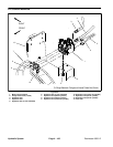
6. Remove the two (2) flange head screws from under
the manifold that secure the manifold to the frame.
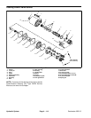
NOTE: Refer to Lift Control Manifold Service in this
chapter for information on hydraulic fitting and cartridge
valve removal and installation.
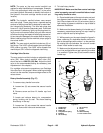
IMPORTANT: A flow control orifice is located be-
neath many of the fittings in the lift control manifold
ports. If any of the fittings is removed from the man-
ifold, make sure to remove orifice and label its posi-
tion for assembly purposes. When installing the
orifice in the manifold, make sure that the orifice is
flat in the base of the port. Manifold damage is pos-
sible if the orifice is cocked in the port.
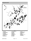
Installation (Fig. 69)
1. Install lift control manifold to the frame.
2. Remove caps and plugs from fittings and hoses.
Properly connect hydraulic lines to lift control manifold
(see Hydraulic Hose and Tube Installation in this chap-
ter).
3. Connect wire harness electrical connectors to the
solenoid valve coils on the lift control manifold.
4. Make sure hydraulic tank is full. Add correct oil if nec-
essary before returning machine to service.
Hydraulic
System