


Reelmaster 3550−DGroomer Page 8 − 8
2. Install groomer plate assembly to groomer non−
drive side of cutting unit:
A. Apply a thin layer of grease to inner lip of seal and
carefully position non−drive side groomer plate onto
groomer shaft and slide to cutting unit.
B. Apply antisieze lubricant to the outside diameter
of the pivot hub and position pivot hub to cutting unit
(Fig. 6).
C. Apply Loctite to two (2) socket head screws and
secure pivot hub to cutting unit side plate.
D. Install shoulder bolt and spacer that secures
quick−up ball joint rod to groomer plate. Torque
Shoulder bolt from 17 to 21 ft−lb (23 to 28 N−m).
E. Install hydraulic reel motor to cutting unit (see Hy-
draulic Reel Motor Installation in Chapter 7 − Cutting
Units in this manual).
3. Install groomer plate assembly to groomer drive side
of cutting unit:
A. Position groomer shim to cutting unit side plate.
B. Apply a thin layer of grease to inner lip of seals
and carefully position drive side groomer plate onto
groomer shaft and slide to cutting unit.
C. Apply antisieze lubricant to the outside diameter
of the pivot hub and position pivot hub to cutting unit
(Fig. 6). Apply Loctite to two (2) socket head screws
and secure pivot hub to cutting unit side plate.
D. Apply antisieze lubricant to the outside diameter
of the pivot hub and position idler plate assembly to
pivot hub.
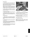
E. Connect extension spring to stud on groomer
plate. Make sure that spring is in the stud groove and
that spring hook is positioned toward the drive pulley.
F. Secure quick−up ball joint rod to drive side
groomer plate with shoulder bolt and spacer. Torque
shoulder bolt from 17 to 21 ft−lb (23 to 28 N−m).
G. Slide pulley spacer and washer(s) onto groomer
shaft.
H. Apply antiseize lubricant to square key that loc-
ates drive pulley. Position key into shaft slot.
NOTE: To prevent cutting reel from turning when in-
stalling drive pulley, block cutting reel with piece of
wood.
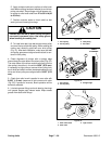
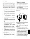
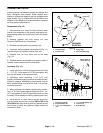
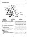
1. Drive pulley
2. Driven pulley
3. Straight edge
Figure 5
2
1
3
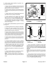
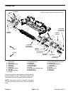
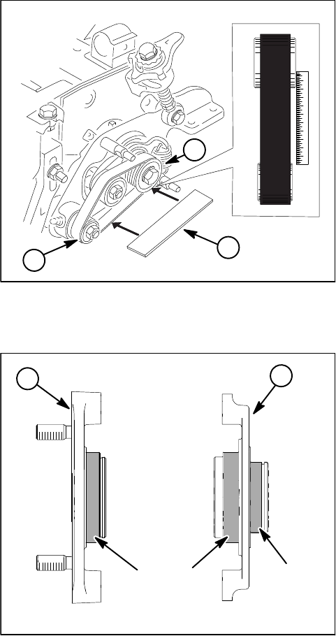
1. Pivot hub
(non−drive side)
2. Pivot hub
(drive side)
Figure 6
2
1
Antiseize
Lubricant
Antiseize
Lubricant
I. Apply Loctite #242 to threads of flange head
screw that secures drive pulley to pivot hub shaft.
Slide drive pulley onto shaft and secure with flange
head screw. Torque screw from 27 to 33 ft−lb (37 to
44 N−m).
NOTE: To prevent groomer shaft from turning when
installing driven pulley, use wrench on groomer shaft
flats.
J. Apply antiseize lubricant to splines of driven pul-
ley and slide driven pulley onto groomer shaft. Se-
cure driven pulley with flange nut and torque flange
nut from 27 to 33 ft−lb (37 to 44 N−m).