


Reelmaster 3550−D
Cutting Units
Page 7 − 32
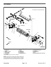
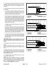
Rear Roller
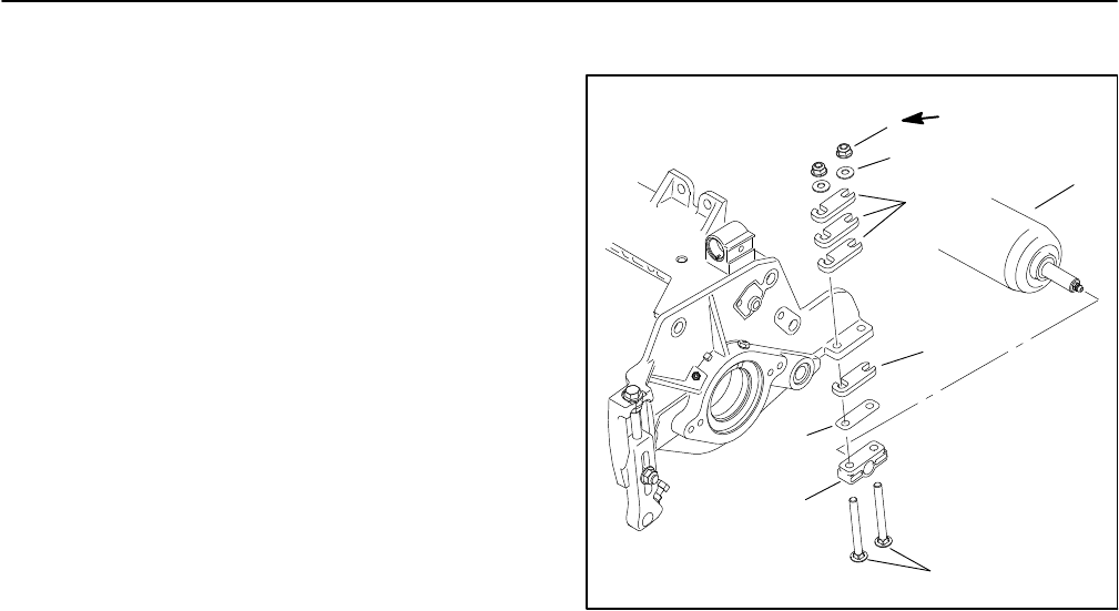
Removal (Fig. 41)
1. Position machine on a clean and level surface, lower
cutting units, stop engine, engage parking brake and re-
move key from the ignition switch.
2. Remove the cutting unit from the machine and place
on a level working surface. Place support blocks under
bedbar to raise rear roller from work surface.
3. Loosen flange nuts that secure the rear roller shaft
to the rear roller brackets.
4. Remove flange nuts and carriage screws that secure
rear roller bracket and roller shims to one of the cutting
unit side plates.
NOTE: On cutting units equipped with optional High
Height of Cut Kit, there will be additional roller shims
installed between rear roller bracket and cutting unit
side plate.
5. Remove the roller bracket and roller shims from the
rear roller and cutting unit.
6. Slide the rear roller assembly from the remaining
rear roller bracket on the cutting unit.
7. If necessary, remove the second rear roller bracket
and roller shims from the cutting unit.
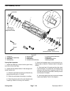
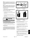
Installation (Fig. 41)
1. Place cutting unit on a level working surface.
NOTE: Refer to Cutting Unit Operator’s Manual for
number of roller shims required for various height of cut
settings.
NOTE: A 0.010” shim (part number 107−4001) is avail-
able to allow for leveling of the rear roller (see Leveling
Rear Roller in the Set−up and Adjustments section of
this chapter). If necessary, this shim would be used on
one side of the rear roller and should be installed be-
tween the rear roller bracket and roller shim.
2. If both rear roller brackets were removed from cutting
unit side plate, position brackets and roller shims to one
of the side plates, and install two (2) carriage screws and
flange nuts to retain bracket in position. Install slotted
roller shims as shown (Fig. 41). Do not fully tighten
flange nuts.
1
2
3
4
7
8
6
5
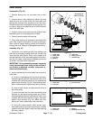
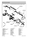
1. Rear roller assembly
2. Rear roller bracket
3. Carriage screw (4)
4. Flange nut (4)
5. Flat washer (4)
6. Roller shims (in storage
above side plate)
7. Roller shims (in use
below side plate)
8. 0.010” shim (if needed)
Figure 41
15 to 19 ft−lb
(20 to 26 N−m)
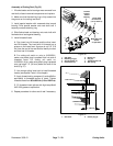
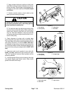
3. Slide rear roller shaft into the rear roller bracket at-
tached to the cutting unit.
4. Slide second rear roller bracket onto the other end of
roller shaft. Secure second roller bracket and shims to
cutting unit side plate with two (2) carriage screws and
flange nuts. Install slotted roller shims as shown
(Fig. 41). Do not fully tighten flange nuts.
5. Center rear roller to the cutting reel and secure in
place by tightening flange nuts. Torque flange nuts from
15 to 19 ft−lb (20 to 26 N−m).
6. Lubricate rear roller.
7. Adjust cutting unit (see Cutting Unit Operator’s
Manual).