


Reelmaster 3550−D
Cutting Units
Page 7 − 25
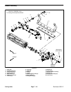
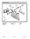
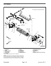
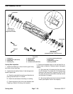
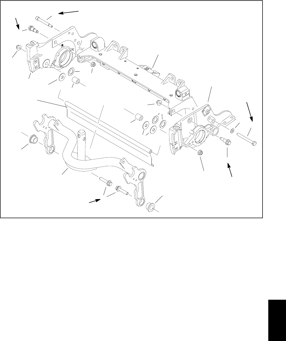
1. Frame
2. LH side plate
3. RH side plate
4. Shoulder bolt (4)
5. Carrier frame
6. Flange head screw (2)
7. Flange bushing (2)
8. Rear grass shield
9. Spacer (2)
10. Shim (as required)*
11. Flange nut (2)
12. Flange nut (4)
13. Special screw
14. Flat washer
15. Cap screw
16. Shim (as required)
Figure 33
15 to 19 ft−lb
(20 to 25 N−m)
27 to 33 ft−lb
(37 to 44 N−m)
1
2
3
4
4
5
6
7
7
8
9
9
16*
10*
11
12
12
11
13
14
15
27 to 33 ft−lb
(37 to 44 N−m)
27 to 33 ft−lb
(37 to 44 N−m)
15 to 19 ft−lb
(20 to 25 N−m)
10
16
*Used on cutting units prior to serial no. 315000001.
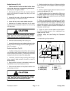
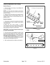
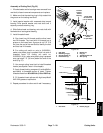
Removal (Fig. 32 & 33)
1. Position machine on a clean and level surface, lower
cutting units, stop engine, engage parking brake and re-
move key from the ignition switch.
2. Remove the cutting unit from the machine and place
on a flat work area.
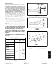
3. If cutting unit is equipped with a counterweight on LH
side plate, remove the two (2) flange nuts securing the
counter weight to the side plate and remove counter
weight from the cutting unit. Remove and discard O−ring
from counter weight.
4. If cutting unit is equipped with an optional groomer or
rear roller brush, remove components for those options
from left hand side plate of cutting unit. See Chapter 8
− Groomer in this manual for additional groomer inform-
ation. See Rear Roller Brush in this chapter for informa-
tion on rear roller brush.
5. Remove bedbar assembly (see bedbar removal in
this chapter).
6. Remove front and rear rollers (see Front Roller Re-
moval and Rear Roller Removal in this chapter).
DPA Cutting
Units