Reelmaster 3550−DPage 6 − 4Chassis
Service and Repairs
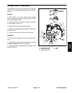
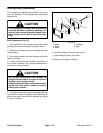
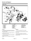
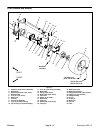
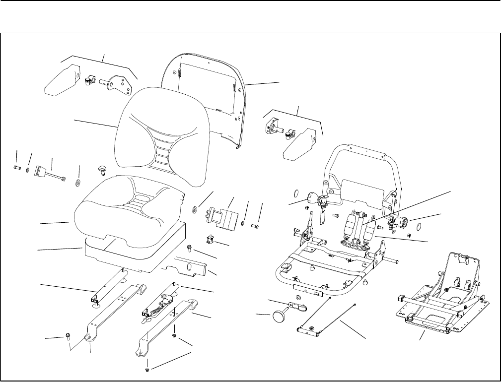
Operator Seat
1. Bottom cushion
2. Back cushion
3. Seat belt
4. Flat washer
5. Flat washer
6. Cap screw
7. Bottom cover
8. Armrest kit
9. Back cover
10. Seat switch
11. Adjusting track − RH
12. Track − LH
13. Support strap
14. Flange nut
15. Knob kit
16. Weight indicator
17. Weight adjust kit
18. Spring and saddle kit
19. Shock absorber kit
20. Knob kit
21. Chassis assembly
22. Heat shield
23. Flange head screw (4)
Figure 4
2
9
8
8
10
6
14
13
12
11
4
3
5
6
20
4
3
1
7
19
20
18
17
15
16
21
5
22
23
23
Removal
1. Park machine on a level surface, lower cutting units,
stop engine, engage parking brake, and remove key
from the ignition switch.
2. Remove heat shield and seat support straps with
seat attached from the frame.
3. Disconnect electrical connector from the seat switch
and remove seat assembly.
4. Remove seat parts as necessary to make repairs
(Fig. 4).
Installation
1. Install any new seat parts (Fig. 4) as a guide.
2. Position seat with support straps attached to the fuel
tank and frame.
3. Attach electrical connector to the seat switch.
4. Secure seat support straps to the frame with four hex
flange head screws.


