


Reelmaster 3550−DPage 5 − 22Electrical System
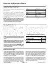
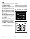
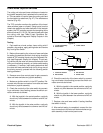
Fuses
The fuse blocks are located under the control panel cov-
er on the right side of the machine.
Fuse Identification and Function
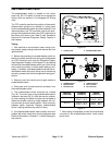
Use the fuse decal (Fig.17) and fuse block (Fig. 18) to
identify each individual fuse and its correct amperage.
The fuses have the following function:
Upper, rear fuse 1 (2 amp) protects logic power circuit
to the TEC controller.
Upper fuse 2 (7.5 amp) protects TEC output power
supply for start relay, fuel stop solenoid, fuel pump, glow
relay, glow plug indicator light and console diagnostic
light. If this fuse is faulty, a fault should be displayed by
the diagnostic light on the control panel (see Diagnostic
Light in this chapter).
Upper fuse 3 (7.5 amp) protects TEC output power
supply for cutting unit proportional relief valve (PRV), lift/
lower enable solenoid (S1) and lift/lower solenoid (S2).
If this fuse is faulty, a fault should be displayed by the
diagnostic light on the control panel (see Diagnostic
Light in this chapter).
Upper, front fuse 4 (7.5 amp) protects TEC output
power supply for front cutting unit lift solenoid (S3), rear
cutting unit lift solenoid (S4), alternator indicator light
and over temperature indicator light. If this fuse is faulty,
a fault should be displayed by the diagnostic light on the
control panel (see Diagnostic Light in this chapter).
Lower, rear fuse 1 (15 amp) protects parking brake
switch, hour meter, alternator, low oil pressure light.
Lower fuse 2 (10 amp) protects engine starter circuit.
Lower fuse 3 (10 amp) protects power point circuit.
Lower, front fuse 4 (10 amp) protects worklight circuit.
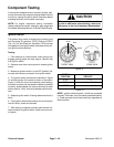
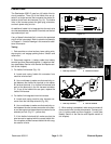
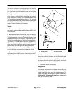
Fuse Testing
Remove cover from control panel to access fuse blocks.
Turn ignition switch to the ON position (do not start en-
gine). With the fuse installed in the fuse block, use a
multimeter to verify that 12 VDC exists at both of the ter-
minal test points on the fuse. If 12 VDC exists at one of
the fuse test points but not at the other, the fuse is faulty.
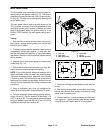
If necessary, make sure that ignition switch is OFF and
key is removed from switch. Remove fuse from fuse
block and check that fuse has continuity across the fuse
terminals.
Figure 17
Figure 18
FRONT
10A
10A
10A
2A
7.5A
7.5A
7.5A
15A
REAR
12 34