


Reelmaster 3550−DPage 5 − 38Electrical System
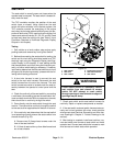
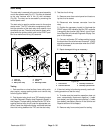
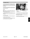
Fuel Pump
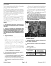
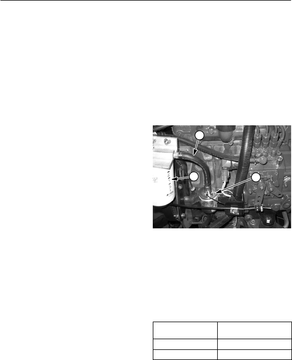
The fuel pump is attached to the left side of the engine
near the fuel/water separator (Fig. 41).
The TEC controller energizes and monitors the opera-
tion of the fuel pump when specific input conditions are
met. The fuel pump is energized when the ignition switch
is set to RUN or START. The fuel pump includes an in-
ternal pressure switch that energizes and de−energizes
the pump to maintain fuel line pressure.
NOTE: The TEC output circuit that controls the electric
fuel pump also controls the fuel stop solenoid. This cir-
cuit is known as the Energize To Run (ETR) circuit. Refer
to the Electrical Schematics and Wire Harness Draw-
ings in Chapter 8 − Foldout Drawings in this manual for
additional information.
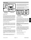
Testing
1. Park machine on a level surface, lower cutting units,
stop engine, and engage parking brake. Unlatch and
raise hood.
2. Test the ETR circuit as a TEC electrical output using
the Diagnostic Display (see Diagnostic Display in this
chapter). If output testing verifies that the TEC is ener-
gizing the ETR circuit under the appropriate conditions,
leave the diagnostic display connected test the circuit
wiring.
3. Test the circuit wiring:
A. Disconnect wire harness connector from the fuel
pump.
B. Position the necessary input(s) to illuminate the
ETR output LED indicating that the TEC controller is
energizing that function (see Table 3: Input Condi-
tions Required to Illuminate Diagnostic Display Out-
puts in this chapter).
C. Connect multimeter (DC voltage setting) across
the terminals of the wire harness connector. 12VDC
should be present at the connector when the ETR
LED is illuminated.
D. Repair damaged wiring as necessary.
4. If the circuit wiring is functioning correctly, use the fol-
lowing procedure to test the pump.
A. Disconnect electrical connector from the fuel stop
solenoid to prevent the engine from starting.
B. Disconnect the fuel hose between the pump and
the filter/separator (pump discharge) at the filter sep-
arator.
C. Make sure fuel hoses to and from the fuel pump
are not kinked, damaged, and free of obstructions.
D. Place disconnected fuel hose into a graduated
cylinder with at least a 1 quart (0.95 liter) capacity.
IMPORTANT: When testing the fuel pump, DO
NOT turn ignition switch to START.
E. Collect fuel in the graduated cylinder by turning
ignition switch to the RUN position. Allow pump to
run for time listed below, then return switch to OFF.
The amount of fuel collected in the graduated cylin-
der should be approximately 21 to 37 fl oz (0.62 to
1.1 Ltr) after thirty (30) seconds.
1. Fuel pump
2. Fuel hose (discharge)
3. Fuel filter
Figure 41
2
1
3
5. Replace fuel pump as necessary. Reconnect fuel
hose to the fuel filter/separator.
6. Reconnect electrical connector to the fuel stop sole-
noid.
7. Bleed fuel system.
Fuel Pump Specifications
Pump Capacity
42 to 74 fl oz/min
(1.2 to 2.2 Ltr/min)
Pressure 2.3 psi (15.8 kPa)
Max. Current Draw 1.8 amp