


Reelmaster 3550−D
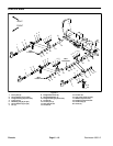
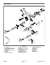
Cutting Units
Page 7 − 4
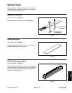
Cutting Unit Installation
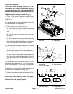
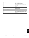
IMPORTANT: When installing cutting unit to ma-
chine, make sure that turf compensator spring is
mounted on the same side of the cutting unit as the
hydraulic reel drive motor. Also, make sure that cut-
ting unit is installed on machine with motor and
weight properly orientated to machine (Fig. 6).
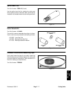
1. Lower all the lift arms completely. Make sure the
snapper pin and cap are removed from the lift arm pivot
yoke (Fig. 4).
2. Position cutting unit to machine. Coat the cutting unit
carrier frame shaft with clean grease.
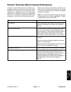
3. Install cutting unit to lift arm pivot yoke:
A. Slide cutting unit under the lift arm while inserting
the carrier frame shaft up into the pivot yoke on lift
arm.
B. Place the cap over the carrier frame shaft and
pivot yoke.
C. Secure the cap and the carrier frame shaft to the
pivot yoke with the snapper pin. Use the pivot yoke
slot if a steering cutting unit is desired or use the yoke
hole if the cutting unit is to be locked in position.
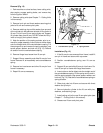
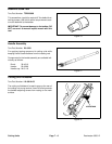
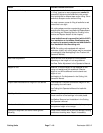
4. For rear cutting units when the height of cut is above
3/4 inch (1.2 cm) use the following procedure:
A. Slide the pivot yoke onto the cutting unit carrier
frame shaft and secure with cap and snapper pin as
described in step 3.
B. Make sure that thrust washer is positioned on the
pivot yoke shaft. Insert the yoke arm shaft into the lift
arm and secure it with the washer and lynch pin
(Fig. 5).
5. Secure the lift arm chain to the cutting unit chain
bracket with the snapper pin (Fig. 2). Use the number of
chain links described in the cutting unit Operator’s
Manual.
6. Move hair pin to the rear hole of turf compensator rod
to unlock the turf compensator spring (Fig. 3).
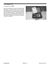
7. Install reel motor to cutting unit (see Hydraulic Reel
Motor in this section).
IMPORTANT: After installing cutting reel motor,
make sure that the reel motor hoses are not twisted,
kinked or in the risk of being pinched.
1. Pivot yoke
2. Cap
3. Snapper pin
4. Carrier frame shaft
Figure 4
1
2
3
4
1. Rear lift arm
2. Lynch pin and washer
3. Pivot yoke shaft
Figure 5
2
1
3
1. Reel motor location 2. Weight location
Figure 6
FRONT
3
4
5
1
2
1
2
2
1
1
2 1
1