


Reelmaster 3550−DPage 5 − 48Electrical System
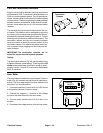
Battery Service
The battery is the heart of the electrical system. With
regular and proper service, battery life can be extended.
Additionally, battery and electrical component failure
can be prevented (see Battery Storage and Battery
Care in this chapter).
CAUTION
Use extreme caution to avoid splashing or spil-
ling battery electrolyte. Electrolyte can destroy
clothing and burn skin or eyes. Always wear
safety goggles and a face shield when working
with batteries.
Battery Specifications
BCI Group 55 Battery
570 Amp Cranking Performance at 0
o
F (−18
o
C)
90 minute Reserve Capacity at 80
o
F (27
o
C)
Electrolyte Specific Gravity (fully charged): from 1.250
to 1.280
Electrolyte Specific Gravity (discharged): 1.240
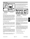
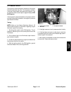
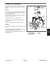
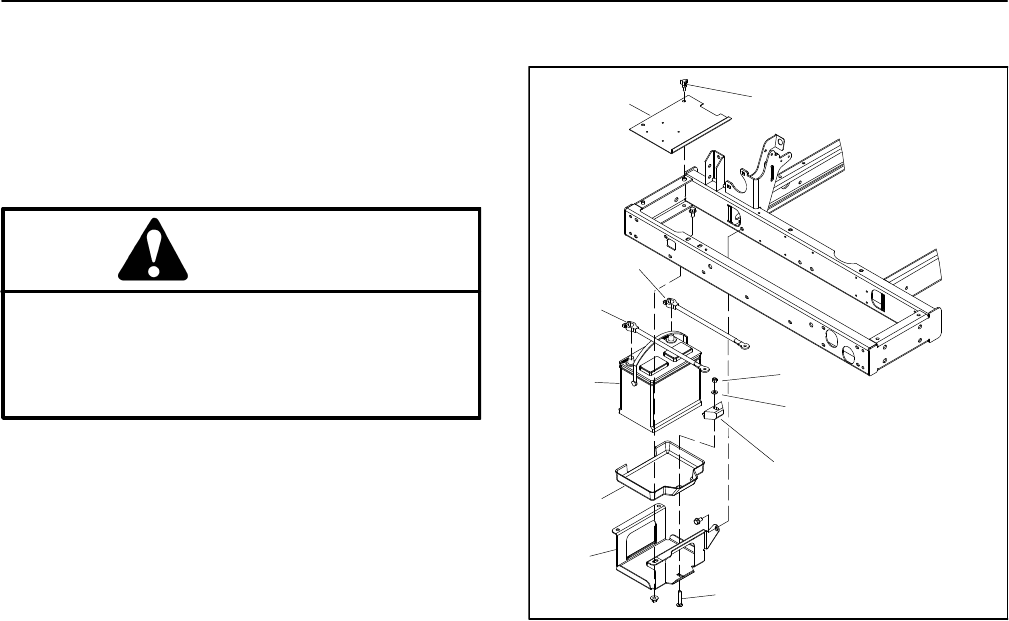
Battery Removal and Installation (Fig. 53)
1. Remove battery cover from the frame. Loosen bat-
tery retainer securing the back of the battery to the bat-
tery support.
2. Note battery cable routing and loosen nut on ground
cable (−) post and remove cable from battery. This
should prevent short circuiting the battery, other compo-
nents, or the operators hands.
3. Note battery cable routing and loosen nut on positive
(+) cable post and remove cable from battery.
4. Carefully remove battery from machine.
5. Install battery in reverse order making sure to con-
nect and tighten positive cable to battery before con-
necting the negative cable. Route battery cables as
noted during removal.
NOTE: Before connecting the negative (ground) cable,
connect a digital multimeter (set to amps) between the
negative battery post and the negative (ground) cable
connector. The reading should be less than 0.1 amp. If
the reading is 0.1 amp or more, the machine’s electrical
system should be tested for short circuits or faulty com-
ponents and repaired.
6. Make sure that rubber boot is properly placed over
positive cable end and positive battery post.
7. Secure battery cover after installing battery.
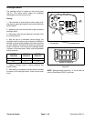
1. Knob (2)
2. Battery cover
3. Negative cable
4. Positive cable
5. Lock nut
6. Flat washer
7. Battery retainer
8. Carriage screw
9. Battery support
10. Battery
11. Battery tray
Figure 53
2
3
6
8
9
10
11
1
5
7
4
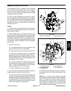
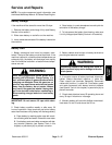
Battery Inspection and Maintenance
1. Replace battery if case is cracked or leaking.
2. Check battery terminal posts for corrosion. Use wire
brush to clean corrosion from posts.
IMPORTANT: Before cleaning the battery, tape or
block vent holes to the filler caps and make sure the
caps are on tightly.
3. Check for signs of wetness or leakage on the top of
the battery which might indicate a loose or missing filler
cap, overcharging, loose terminal post or overfilling.
Also, check battery case for dirt and oil. Clean the bat-
tery with a solution of baking soda and water, then rinse
it with clean water.
4. Check that the cover seal is not broken away. Re-
place the battery if the seal is broken or leaking.
5. Check the electrolyte level in each cell. If the level is
below the tops of the plates in any cell, fill all cells with
distilled water between the minimum and maximum fill
lines. Charge at 15 to 25 amps for fifteen (15) minutes
to allow sufficient mixing of the electrolyte.