


Reelmaster 3550−D Hydraulic SystemPage 4 − 19
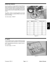
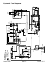
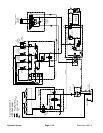
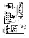
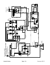
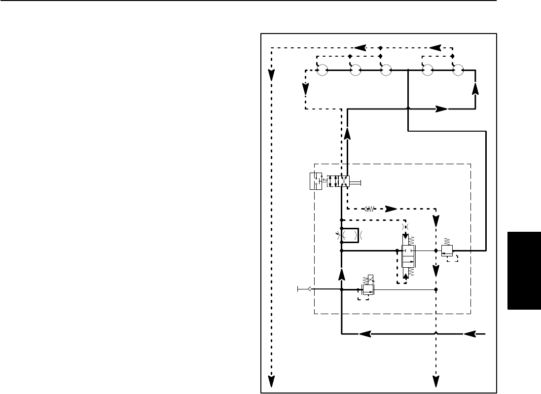
Cutting Unit Circuit
Mow
The tandem gear pump is directly coupled to the piston
pump/hydrostat which is belt driven by the engine. The
front section of the gear pump (P1) supplies hydraulic
flow for the cutting unit circuit. The gear pump takes its
suction from the hydraulic tank.
Proportional relief valve (PRV) in the mow control mani-
fold is de−energized with the engine running when ei-
ther the reel enable/disable switch is in the DISABLE
position, the cutting units are raised or the mow/trans-
port slide is in the TRANSPORT position. The de−ener-
gized PRV allows gear pump flow directly to the
hydraulic tank by−passing the reel motors so the cutting
reel blades remain stationary.
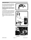
Proportional relief valve (PRV) is energized by the TEC
controller with the engine running when the reel enable/
disable switch is in the ENABLE position, the cutting
units are down and the mow/transport slide is in the
MOW position. In the energized position, this valve di-
rects gear pump oil flow toward the reel motors and also
functions as the relief valve for the front reel motors.
Maximum front reel motor pressure is 3000 PSI (207
bar). Front reel motor circuit pressure can be monitored
at the test fitting in mow control manifold port G.
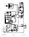
When the mow circuit is engaged, oil flow from manifold
port P flows through the flow control valve (FC) used to
adjust reel speed. With the backlap valve (MV) in the
MOW position, oil flows through the backlap valve (MV),
out the manifold port (M1), and to the reel motors that
are connected in series. Any excess flow above the flow
control valve setting is by−passed to the reservoir
through the logic cartridge valve (LC). The logic cart-
ridge valve (LC) reduces fluctuations in reel speed by
compensating for pressure variations across the flow
control valve (FC).
Mow circuit oil flows through the front reel motors and
then the rear reel motors as it turns the motors in the
mow direction. Manifold relief valve (RV) provides relief
protection for the rear reel motors at a pressure less
than the proportional relief valve (PRV). If pressure to
the rear motors reaches 1500 PSI (103 bar), relief valve
(RV) opens.
Oil flow from the reel motors returns into mow control
manifold port (M2), through backlap valve (MV), through
manifold check valve CV1 and exits the manifold
through pot (T). Oil returns to the hydraulic tank through
the oil cooler and oil filter.
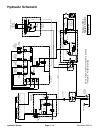
Figure 21
.73
BACKLAP
SWITCH
(SW)
REEL #4
LC
FC
PRV
MV
T
M1
P
G
M2
MOW CONTROL
MANIFOLD
.73 .73 .73 .73
CV1
1500 PSI
M3
REEL #1 REEL #5 REEL #2 REEL #3
FROM GEAR
PUMP
TO OIL
COOLER
TO HYDRAULIC
TANK
RV
OR1
.050”
OR2
.020”
3000 PSI
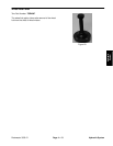
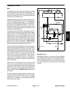
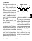
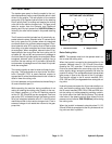
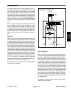
Backlap (Fig. 21)
Backlapping operation is the similar to mowing opera-
tion, except for the position of the backlap valve (MV).
When the backlap valve (MV) is in the BACKLAP posi-
tion, oil flows through the rear reel motors and then the
front reel motors as it turns the motors in the backlap
direction.
Hydraulic
System