


Reelmaster 3550−D Hydraulic SystemPage 4 − 77
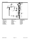
7. Label all hydraulic hoses and fittings for assembly
purposes.
8. Disconnect all hydraulic hoses connected to the hy-
draulic fittings on the piston pump/hydrostat and gear
pump. Allow hoses to drain into a suitable container.
Plug hose and fitting openings to prevent contamina-
tion.
CAUTION
Support pump assembly during removal to pre-
vent them from falling and causing personal in-
jury or component damage.
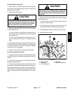
9. Support hydraulic pump assembly to prevent it from
shifting.
10.Remove both flange head screws and flange nuts
that secure pump support to engine mount.
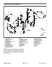
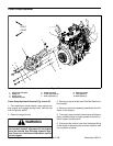
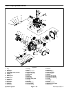
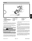
11.Remove fasteners and spacers securing the pump
mount plate to the engine (Fig. 47). Note location of cap
screws, washers and spacers for assembly purposes.
12.Carefully remove pump mount plate with pumps,
pulley, pump support and idler assembly from the ma-
chine.
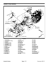
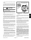
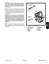
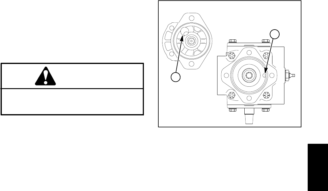
NOTE: A case drain exists in the piston pump/hydrostat
and a suction port is near the input shaft of the gear
pump (Fig. 48). When the gear pump is removed from
the piston pump/hydrostat, plug both case drain holes to
prevent draining the pumps.
13.Remove both cap screws and flat washers securing
gear pump to the piston pump. Separate gear pump
from the piston pump. Locate and retrieve O−ring. Plug
openings of gear pump to prevent contamination.
14.Remove pump pulley from the taper lock bushing on
the piston pump shaft:
A. Remove three (3) cap screws and lock washers
securing pulley to the taper lock bushing.
IMPORTANT: Excessive or unequal pressure on
the cap screws can break the bushing flange.
B. Insert cap screws into threaded removal holes of
the pulley. Tighten screws progressively and evenly
until the pulley is loose on the bushing. Remove
pulley from the bushing.
15.Loosen set screw that secures taper lock bushing to
piston pump shaft. Remove bushing from the pump
shaft. Locate and retrieve key from pump shaft.
1. Piston pump/hydrostat
case drain
2. Gear pump suction por
t
Figure 48
Remove plugs before installing
gear pump to piston pump
2
1
16.Remove both cap screws and washers that secure
piston pump to pump support. Locate and retrieve
spacers.
17.Remove lock nuts, flat washers and cap screws that
secure the piston pump to the pump mount plate. Re-
move pump from plate.
18.If hydraulic fittings are to be removed from piston
pump, mark fitting orientation to allow correct assembly.
Remove hydraulic fittings and O−rings from the piston
pump as needed. Discard removed O−rings.
Piston Pump Installation (Fig. 44 and 47)
1. Position and secure piston pump to the pump mount
plate with cap screws, flat washers and lock nuts.
2. Lubricate and place new O−rings onto all removed
pump fittings. Install fittings into pump openings using
marks made during the removal process to properly
orientate fittings. Tighten fittings (see Hydraulic Fitting
Installation in this chapter).
IMPORTANT: A case drain exists in the piston
pump/hydrostat and a suction port is near the input
shaft of the gear pump (Fig. 48). Before the gear
pump is installed to the piston pump, make sure that
plugs placed in either of these ports are removed.
Failure to remove plugs will cause excessive pres-
sure in the piston pump and damage seals. Also, be-
fore installing gear pump to piston pump, fill piston
pump housing with clean hydraulic oil through case
drain hole.
3. Install and secure gear pump to the piston pump (see
Gear Pump in this chapter).
Hydraulic
System