


Reelmaster 3550−DPage 5 − 28Electrical System
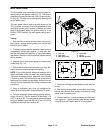
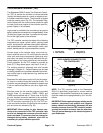
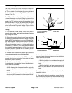
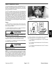
Lower/Raise Joystick Switches
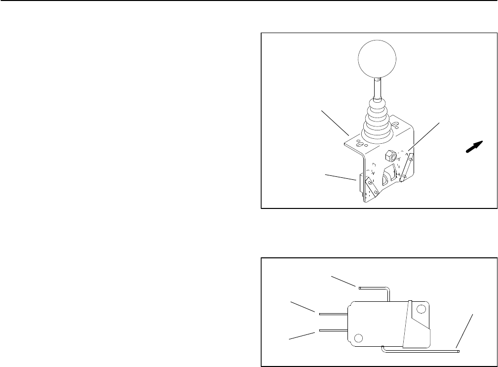
The cutting unit raise and lower switches are located on
the joystick assembly that is attached to the control pan-
el. The rear switch is used to lower the cutting units and
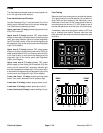
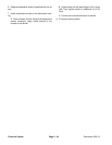
the front switch to raise them (Fig. 27). The switches are
identical (Fig. 28).
The TEC controller monitors the position of the lower/
raise switches (open or closed). Using inputs from the
lower/raise switches and other switches in the interlock
system, the TEC controller controls the energizing of the
solenoid valves (S1, S2, S3, S4) used to lower and raise
the cutting units (see Table 3: Input Conditions Re-
quired to Illuminate Diagnostic Display Outputs in this
chapter).
Testing
1. Park machine on level surface, lower cutting units if
possible, stop engine, apply parking brake and remove
key from ignition switch.
2. Before disconnecting the raise and lower switches
for testing, the switches and their circuit wiring should be
tested as TEC electrical inputs using the Diagnostic Dis-
play (see Diagnostic Display this chapter). If input test-
ing verifies that the raise and lower switches and circuit
wiring are functioning correctly, no further switch testing
is necessary. If, however, input testing determines that
the raise and lower switches and circuit wiring are not
functioning correctly, proceed with the following switch
testing procedure.
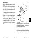
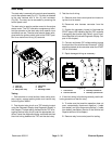
3. Remove cover from control panel to gain access to
raise and lower switches on joystick assembly.
4. Make sure ignition switch is in the OFF position. Dis-
connect wire harness connectors from raise and lower
switches on joystick assembly.
5. Check the continuity of the raise switch by connect-
ing a multimeter (ohms setting) across the switch con-
nector terminals as follows:
A. With the joystick in the neutral position, continuity
should only exist between the common and NC ter-
minals.
B. With the joystick in the raise position, continuity
should only exist between the common and NO ter-
minals.
1. Joystick assembly
2. Raise switch
3. Lower switch
Figure 27
1
2
3
FRONT
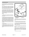
1. Common terminal
2. NO terminal
3. NC terminal
4. Switch lever
Figure 28
1
2
3
4
6. Check the continuity of the lower switch by connect-
ing a multimeter (ohms setting) across the switch con-
nector terminals as follows:
A. With the joystick in the neutral position, continuity
should only exist between the common and NC ter-
minals.
B. With the joystick in the lower position, continuity
should only exist between the common and NO ter-
minals.
7. Replace raise and lower switch if testing identifies
that switch is faulty.
8. After switch testing is completed, connect the har-
ness connectors to the raise and lower switches on joy-
stick assembly. Install control panel cover.