


Reelmaster 3550−D
Cutting Units
Page 7 − 19
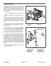
Bedbar Removal (Fig. 23)
1. Position machine on a clean and level surface, lower
cutting units, stop engine, engage parking brake and re-
move key from the ignition switch.
2. Remove the cutting unit from the machine. Use the
cutting unit kickstand to support the cutting unit (see
Special Tools).
3. Loosen the lock nuts on the end of each bedbar ad-
juster assembly until washers are loose.
4. Loosen the lock nuts on each bedbar pivot bolt.
5. Remove two (2) bedbar pivot bolts, two (2) metal
washers and four (4) plastic washers from the cutting
unit side plates.
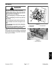
CAUTION
Contact with the reel, bedknife or other cutting
unit parts can result in personal injury. Use
heavy gloves when handling the bedbar.
6. Remove bedbar assembly from cutting unit.
7. Inspect flange bushings and rubber bushings in side
plates for wear or damage. Remove bushings and re-
place if necessary.
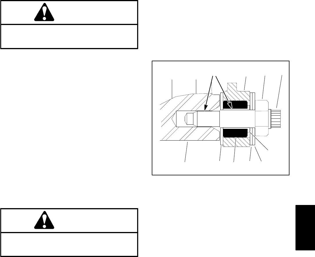
Bedbar Installation (Fig. 23)
1. If rubber bushing was removed from either cutting
unit side plate, apply antiseize lubricant to the side plate
bore and install a new bushing. The bushing should be
installed flush with the inside of the side plate.
2. If removed, install the flange bushings with flange
facing outward. Apply antiseize lubricant to inside of
flange bushing.
3. Apply antiseize lubricant to the bedbar threads and
the shoulder area of each bedbar pivot bolt.
4. Slide one metal washer and one plastic washer onto
each bedbar pivot bolt.
CAUTION
Contact with the reel, bedknife or other cutting
unit parts can result in personal injury. Use
heavy gloves when handling the bedbar.
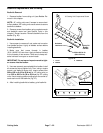
5. Position bedbar into cutting unit. Make sure that the
top of each bedbar arm is between washer and adjuster
screw flange.
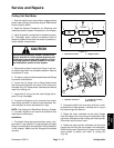
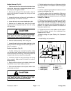
6. Position a plastic washer between bedbar and each
cutting unit side plate (Fig. 24).
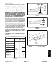
7. Install the bedbar pivot bolt assemblies. Make sure
that plastic washers are not caught on the threads of the
pivot bolts. Tighten each bedbar pivot bolt from 27 to 33
ft−lbs (37 to 44 N−m).
8. Tighten the pivot bolt lock nuts equally, on each side,
until the outer steel washers cannot be rotated by hand.
Then, loosen the lock nuts slightly so the outer steel
washers just rotate by hand, yet no bedbar end play is
present. The plastic washer between the bedbar and
side plate may be loose.
9. Tighten the lock nut on each bedbar adjuster assem-
bly until the adjuster spring is fully compressed, then
loosen lock nut 1/2 turn.
10.Adjust cutting unit (see Cutting Unit Operator’s
Manual).
11.Install cutting unit to machine.
1
2
3
46
78
54
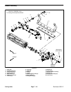
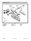
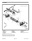
1. Cutting unit side plate
2. Rubber bushing
3. Flange bushing
4. Washer (plastic)
5. Washer (metal)
6. Bedbar
7. Bedbar pivot bolt
8. Lock nut
Figure 24
Antiseize
Lubricant
DPA Cutting
Units