


Reelmaster 3550−D Page 5 − 13 Electrical System
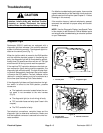
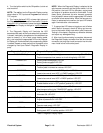
6. The automatic cutting unit Lower Sequence or Raise
Sequence (programed into the TEC controller) ener-
gizes and de−energizes outputs 5 thru 10 in a predeter-
mined order. Operation of the program sequence can be
checked using the diagnostic display by meeting the in-
put conditions required for these outputs, setting the reel
enable/disable switch to the ENABLE position, and mo-
mentarily moving the joystick to RAISE or LOWER. The
output LEDs will illuminate during the sequence and ex-
tinguish when the sequence is completed, with one ex-
ception. The LED for output 7 (Front Mow (SP)) will
remain illuminated after the Lower Sequence has com-
pleted.
7. If the output LED illuminates as specified, but the ma-
chine does not function properly, suspect a failed electri-
cal component, an open condition in the tested circuit or
a non-electrical problem (e.g. hydraulic component
problem). Repair as necessary.
8. If each input is in the correct position and functioning
correctly, and the output LED is not illuminating, a TEC
controller problem may exist. If this occurs, contact your
Toro Distributor for assistance.
9. After output functions testing is complete, discon-
nect the Diagnostic Display connector from the wire har-
ness connector and plug loop−back connector into wire
harness. Install cover onto control panel.
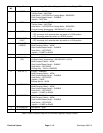
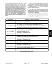
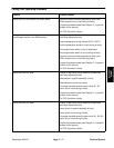
Output Name
Diagnostic Display LED Operation
START Start Relay energized: LED ON
Start Relay de−energized: LED OFF
ETR Fuel Pump and Fuel Stop solenoid (HOLD) energized: LED ON
Fuel Pump and Fuel Stop solenoid (HOLD) de−energized: LED OFF
GLOW Glow Relay, Glow Plugs, and Glow Plug Indicator Light energized: LED ON
Glow Relay, Glow Plugs, and Glow Plug Indicator Light de−energized: LED OFF
DIAGNOSTIC LIGHT Diagnostic Light energized: LED ON
Diagnostic Light de−energized: LED OFF
SV1 (LIFT/LOWER) Solenoid S1 energized: LED ON
Solenoid S1 de−energized: LED OFF
REAR MOW (SV) Not used for this product
FRONT MOW (SP) Proportional Relief Valve (PRV) energized: LED ON
Proportional Relief Valve (PRV) de−energized: LED OFF
SV2 (LIFT) Solenoid S2 energized: LED ON
Solenoid S2 de−energized: LED OFF
SV3 (FRONT EN) Solenoid S3 energized: LED ON
Solenoid S3 de−energized: LED OFF
SV4 (REAR EN) Solenoid S4 energized: LED ON
Solenoid S3 de−energized: LED OFF
ALTERNATOR Charge Indicator Light energized: LED ON
Charge Indicator Light de−energized: LED OFF
OVER TEMP High Temperature Warning Light energized: LED ON
High Temperature Warning Light de−energized: LED OFF
Table 4: Diagnostic Display Outputs
Electrical
System