Reelmaster 3550−DHydraulic System Page 4 − 82
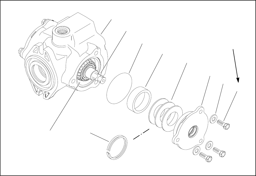
1. Crush ring
2. Shims
3. Cover plate
4. Housing
5. Camplate (control shaft)
6. Bearing cone
7. Bearing cup
8. O−ring
9. Washer (3)
10. Cap screw (3)
Figure 51
29 ft−lb
(39 N−m)
6
4
5
8
7
2
3
9
10
1
Piston Pump/Hydrostat Crush Ring Replacement
(Fig. 51)
NOTE: The shims replace the crush ring in the cover
plate. If the camplate, cover plate or housing is replaced
during servicing of the pump, the old crush ring can not
be used to make sure of proper preload.
1. Remove crush ring from the cover plate. Measure
thickness of crush ring.
2. Stack shims to the thickness of the crush ring.
3. Insert shims into the cover plate in the same location
that the crush ring was removed from.
4. Assemble housing sub assembly consisting of the
housing, camplate, bearing cone, bearing cup and cov-
er plate (see Eaton, Medium Duty Piston Pump, Repair
Information, Model 70160 Variable Displacement Piston
Pump at the end of this chapter).
5. Install washers and cap screws to the cover plate
and housing. Torque cap screws to 29 ft−lbs (39 N−m).
6. Check torque required to rotate control shaft. Torque
should be from 15 to 25 in−lbs (1.7 to 2.8 N−m).
A. If torque is too low, add additional shims and re-
peat steps 3 through 6 until the specified torque is
achieved.
B. If torque is too high, remove shims and repeat
steps 3 through 6 until the specified torque is
achieved.
7. Complete assembly of the pump (see Eaton, Me-
dium Duty Piston Pump, Repair Information, Model
70160 Variable Displacement Piston Pump at the end of
this chapter).


