


Reelmaster 3550−D Page 5 − 9 Electrical System
Diagnostic Display
Reelmaster 3550−D machines are equipped with a Toro
Electronic Controller (TEC) which controls machine
electrical functions. The controller monitors various in-
put switches (e.g. ignition switch, seat switch, neutral
switch) and energizes outputs to actuate solenoids or
relays for the requested machine function.
For the TEC to control the machine as desired, each of
the inputs (switches and sensors) and outputs (sole-
noids and relays) must be connected and functioning
properly.
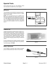
The Diagnostic Display (see Special Tools in this chap-
ter) is a tool to help the technician verify correct electrical
functions of the machine.
IMPORTANT: The Diagnostic Display must not be
left connected to the machine. It is not designed to
withstand the environment of the machine’s every
day use. When use of the Diagnostic Display is com-
pleted, disconnect it from the machine and recon-
nect loop−back connector to harness connector.
The machine will not operate without the loop−back
connector installed on the harness. Store the Diag-
nostic Display in a dry, secure, indoor location and
not on machine.
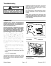
CAUTION
The interlock switches are for the protection of
the operator and bystanders and to ensure cor-
rect operation of the machine. Do not bypass or
disconnect switches. Check the operation of the
interlock switches daily for proper operation. Re-
place any malfunctioning switches before oper-
ating the machine.
Verify Diagnostic Display Input Functions
1. Park machine on a level surface, lower the cutting
units, stop the engine and apply the parking brake.
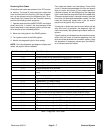
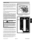
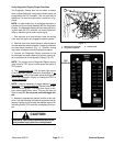
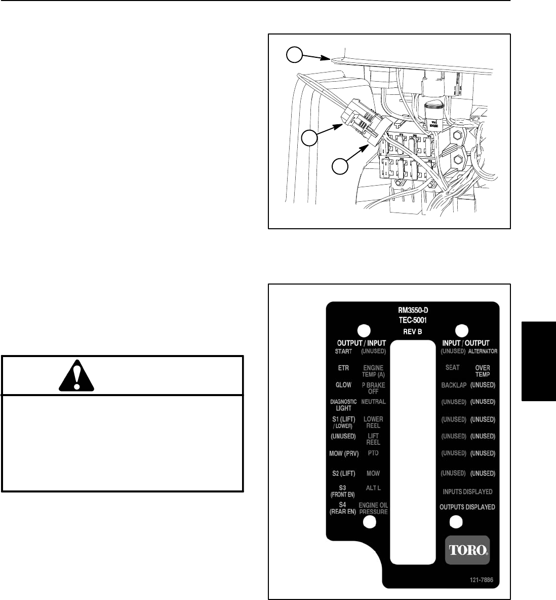
2. Remove cover from control panel to allow access to
wire harness loop−back connector. Locate wire harness
and loop−back connector (Fig. 9). Carefully unplug
loop−back connector from wire harness connector.
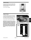
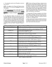
3. Connect the Diagnostic Display connector to the
wire harness connector. Make sure correct overlay de-
cal is positioned on the Diagnostic Display (Fig. 10).
NOTE: When the ignition switch is in the OFF position,
all Diagnostic Display LED’s should be OFF.
1. Wire harness connector
2. Loop−back connector
3. Control panel
Figure 9
1
2
3
Figure 10
TEC
OVERLAY
Electrical
System