


Reelmaster 3550−D Hydraulic SystemPage 4 − 117
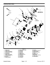
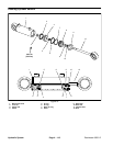
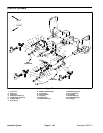
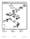
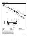
Removal (Fig. 75)
1. Park machine on a level surface. Lower cutting units,
stop engine and engage parking brake. Remove key
from the ignition switch.
NOTE: The rear tire must be removed to allow sufficient
clearance to remove the steering cylinder from the ma-
chine.
WARNING
Before jacking up the machine, review and follow
Jacking Instructions in Chapter 1 − Safety.
2. Jack or lift rear wheel off the ground.
3. Remove rear wheel from the machine.
4. Thoroughly clean hydraulic hose ends and fittings on
steering cylinder to prevent hydraulic system contami-
nation.
WARNING
Before disconnecting or performing any work on
the hydraulic system, all pressure in the system
must be relieved. See Relieving Hydraulic Sys
-
tem Pressure in the General Information section
of this chapter.
5. Label the hydraulic hoses to show their correct posi-
tion on the steering cylinder. Remove hydraulic hoses
from steering cylinder.
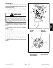
6. Remove two (2) jam nuts from both steering cylinder
ball joints. Remove steering cylinder with ball joints from
machine.
7. If hydraulic fittings are to be removed from steering
cylinder, mark fitting orientation to allow correct assem-
bly. Discard O−rings from removed fittings.
8. If needed, remove ball joints from steering cylinder.
Installation (Fig. 75)
1. If removed, install ball joints into steering cylinder.
2. Lubricate and place new O−rings onto removed
steering cylinder fittings. Install fittings into cylinder
openings using marks made during the removal process
to properly orientate fittings. Tighten fittings (see Hy-
draulic Fitting Installation in this chapter).
3. Install steering cylinder to the frame and rear. When
securing cylinder ball joints to machine, tighten the first
jam nut from 65 to 85 ft−lb (88 to 115 N−m), then tighten
the second jam nut to the same specification.
4. Remove caps and plugs from steering cylinder fit-
tings and hoses. Using labels placed during cylinder re-
moval, properly connect hydraulic lines to steering
cylinder (see Hydraulic Hose and Tube Installation in
this chapter).
5. Secure rear wheel to the machine with four (4) lug
nuts. Lower machine to the ground. Torque wheel lug
nuts in a crossing pattern from 45 to 65 ft−lb (61 to 88
N−m).
6. Make sure hydraulic tank is full. Add correct oil if ne-
cessary.
7. After assembly is completed, operate steering cylin-
der to verify that hydraulic hoses and fittings are not con-
tacted by anything.
Hydraulic
System