


Reelmaster 3550−D Page 5 − 23 Electrical System
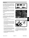
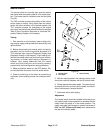
Fusible Links
The Reelmaster 3550−D uses four (4) fusible links for
circuit protection. Three (3) of the fusible links are lo-
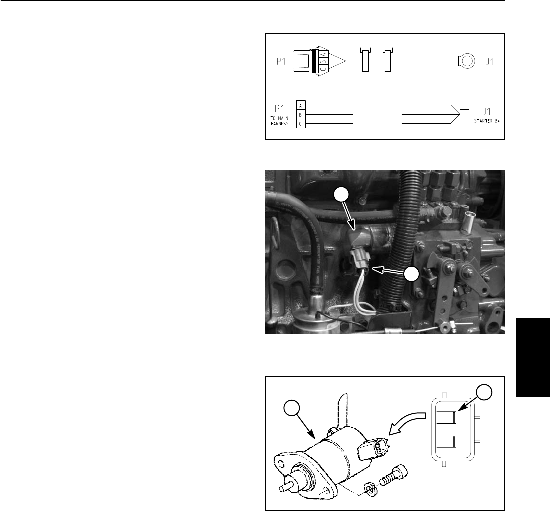
cated in a single harness that connects the starter B+
terminal to the main wire harness (Fig. 19). The fusible
links in this harness protect the glow plug, alternator,
and main power relay circuits.
An additional fusible link is integrated into the main wire
wire harness between the starter G terminal and the fuel
stop solenoid pull coil.
If any of these links should fail, current to the protected
circuit will be interrupted. Refer to electrical schematic
in Chapter 8 − Foldout Drawings in this manual for addi-
tional information.
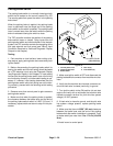
Testing
1. Park machine on a level surface, lower cutting units,
stop engine, and engage parking brake. Unlatch and
raise hood.
2. Disconnect negative (−) battery cable from battery
terminal and then disconnect positive (+) cable from bat-
tery (see Battery Service in the Service and Repairs sec-
tion of this chapter).
3. For fusible link harness (Fig. 19):
A. Locate and unplug fusible link connector from
machine wire harness.
B. Use a multimeter to make sure that continuity ex-
ists between the fusible link terminal on the starter
B+ terminal (terminal J1 on fusible link harness) and
each of the terminals in the link harness connector
P1. If any of the fusible links are open, replace the
fusible link harness.
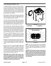
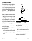
4. For fusible link integrated into wire harness:
A. Locate and unplug machine wire harness con-
nector from the fuel stop solenoid (Fig. 20).
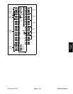
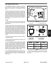
B. Use a multimeter to make sure that continuity ex-
ists between the wire harness connector at the start-
er and the engine fuel stop solenoid connector for the
solenoid pull coil (Fig. 21 − yellow wire).
C. If this fusible link should fail, make sure that the
wire harness is repaired with the correct fusible link.
Do not replace a failed harness fusible link with a reg-
ular section of wire.
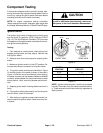
Figure 19
FUSIBLE LINK
FUSIBLE LINK
FUSIBLE LINK
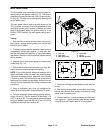
1. Fuel stop solenoid 2. Harness connector
Figure 20
2
1
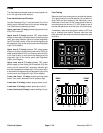
1. Fuel stop solenoid 2. Pull coil terminal
Figure 21
2
1
5. When testing is completed, make sure to connect all
disconnected wire harness components. Connect posi-
tive (+) battery cable and then negative (−) cable (see
Battery Service in the Service and Repairs section of
this chapter).
Electrical
System