


Reelmaster 3550−D Hydraulic SystemPage 4 − 73
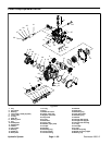
Drive Belt Removal (Fig. 44)
1. Park machine on a level surface. Lower cutting units,
stop engine and engage parking brake. Remove key
from the ignition switch.
2. Raise and support hood.
CAUTION
The torsion spring that tensions the idler as-
sembly is under tension and may cause personal
injury during removal. Use caution when remov-
ing spring end from the pump mount plate.
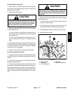
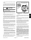
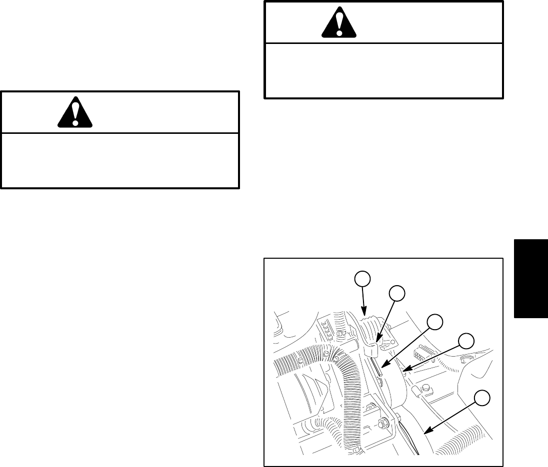
3. Remove pump drive belt tension from torsion spring
on idler arm (Fig. 45).
A. Insert nut driver or small piece of pipe onto the
end of the torsion spring that is secured on the pump
mount plate tab.
B. Push down and forward on the spring end to un-
hook the spring from the tab on the pump mount
plate.
4. Rotate idler pulley away from pump drive belt and re-
move drive belt from pulleys. Make sure that drive belt
is in good condition if it is to be re−installed. Replace
drive belt if worn or damaged.
5. Remove drive belt idler components as needed.
Drive Belt Installation (Fig. 44)
1. Install all removed drive belt idler components. Make
sure that idler pulley and idler arm rotate freely after as-
sembly.
2. Install drive belt onto pulleys. Position idler pulley to-
ward the pump drive belt.
3. Using a straight edge across the lower face of the
pump pulley, verify pump drive belt alignment across en-
gine and pump pulleys. If pulleys are not in alignment,
adjust location of pump pulley on pump shaft so align-
ment is correct (see Piston Pump/Hydrostat in this chap-
ter).
CAUTION
Use caution when installing torsion spring end
onto the pump mount plate. Applying tension to
the spring may cause personal injury during in-
stallation.
4. Apply pump drive belt tension with torsion spring on
idler arm (Fig. 45).
A. Insert nut driver or small piece of pipe onto the
end of the torsion spring.
B. Push down on the spring end and then hook the
spring under the tab on the pump mount plate.
5. Lubricate grease fitting on end of idler pivot shaft.
6. Lower and secure hood.
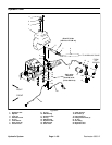
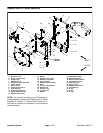
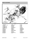
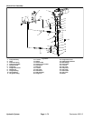
1. Pump drive belt
2. Idler pulley
3. Torsion spring end
4. Spring end
5. Pump mount plate tab
Figure 45
2
1
3
4
5
Hydraulic
System