


Reelmaster 3550−D Hydraulic SystemPage 4 − 37
Traction Circuit Testing − Wheel Motor Efficiency
Test:
Wheel motor efficiency is the second in a series of tests
recommended to determine traction circuit perform-
ance. Hydraulic fluid flow of 1.5 GPM (5.7 LPM) or more
through a stationary wheel motor under load indicates
an internal leak in the wheel motor. A worn wheel motor
is less efficient. Eventually, enough fluid by−pass will
cause the wheel motor to stall under heavy load condi-
tions. Continued operation can generate excessive
heat, cause damage to seals and other components in
the hydraulic system, and affect overall machine per-
formance.
There are moments during wheel motor operation (ger-
oller position) when fluid flow through the motor is less
restricted. If a wheel motor is tested in this position, the
test results will be higher should not be used to determ-
ine wheel motor efficiency. Test wheel motors in three
(3) different wheel positions to obtain accurate test res-
ults. Record test readings for all three (3) wheel posi-
tions.
Hydraulic fluid flows through both front wheel motors (in
parallel) before passing through the rear wheel motor (in
series). In this configuration, the rear wheel motor can
mask front wheel motor performance issues, and the
front wheel motors can mask rear wheel motor perform-
ance issues. Start by testing both front wheel motors to-
gether, then individually if necessary. Finish by testing
the rear wheel motor.
Special Equipment Required:
S Pressure Gauge
S Flow Meter with Pressure Gauge that has at least
an 18 GPM (68 LPM) capacity
S Phototach (non−contact tachometer)
1. Park machine on a level surface with the cutting units
lowered and the reel engage/disengage switch is in the
disengage position. The engine should be off and the
parking brake engaged.
2. Read Precautions for Hydraulic Testing in this
chapter.
3. Make sure that traction pedal is adjusted to the neu-
tral position.
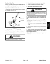
4. Attach a heavy chain to the rear of the machine frame
and an immovable object to prevent the machine from
moving during testing.
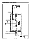
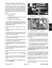
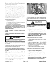
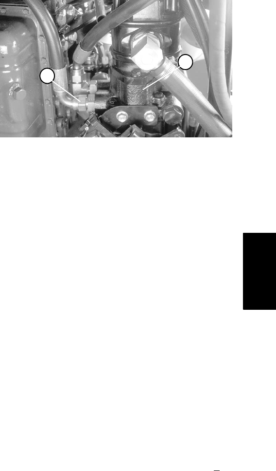
1. Lower hydraulic fitting 2. Piston pump
Figure 28
1
2
Front Wheel Motor Test:s
Hydraulic fluid flows through both front wheel motors (in
parallel) before passing through the rear wheel motor (in
series). To accurately test the front wheel motors, the
rear wheel motor must be removed from the traction cir-
cuit.
1. Disconnect hose from the lower hydraulic fitting on
the bottom of the hydrostat (Fig. 28).
NOTE: An alternate testing location would be at the hy-
draulic hose from the hydrostat and the hydraulic tube
supplying the front wheel motors under the left floor
plate.
2. Install flow tester between the hydrostat and the dis-
connected hose. Make sure the tester flow control valve
is fully open.
3. Disconnect both hydraulic lines from the rear wheel
motor, then reconnect the lines to each other. Plug ports
in wheel motor to prevent contamination.
4. Chock front wheels to prevent wheel rotation.
5. Start engine. Move throttle to full speed (3220 +
50
RPM).
6. Make sure hydraulic fluid is at normal operating tem-
perature by operating the machine for approximately 10
minutes. Make sure the hydraulic tank is full.
Hydraulic
System