


Reelmaster 3550−D
Cutting Units
Page 7 − 15
Service and Repairs
Cutting Unit Reel Motor
1. Park the machine on a level surface, engage parking
brake, lower cutting units and stop engine. Remove key
from the ignition switch.
2. Read the General Precautions for Removing and
Installing Hydraulic System Components in this chapter.
3. Label all hydraulic connections for assembly purpos-
es. Thoroughly clean hydraulic connections prior to
loosening hydraulic lines from reel motor to prevent hy-
draulic system contamination.
CAUTION
Before opening hydraulic system, operate all hy-
draulic controls to relieve system pressure and
avoid injury from pressurized hydraulic oil. See
Relieving Hydraulic System Pressure in the Gen-
eral Information section of this chapter.
4. Disconnect hydraulic hoses from fittings in reel mo-
tor. Allow lines to drain into a suitable container. Remove
and discard O−rings.
5. Put caps or plugs on disconnected hoses and fittings
to prevent contamination.
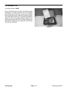
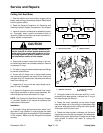
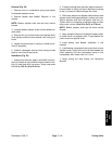
6. Loosen two (2) flange nuts or flange head screws
that secure the hydraulic reel motor to the cutting unit
side plate (Fig. 20). Rotate motor clockwise and remove
motor from cutting unit.
7. Inspect the O−ring on the reel motor flange and re-
place O−ring if damaged.
8. If hydraulic fittings are to be removed from motor,
mark fitting orientation to allow correct assembly. Re-
move fittings from motor and discard O−rings.
NOTE: See Cutting Unit Reel Motor Service in Chapter
4 − Hydraulic System in this manual for additional reel
motor service information.
Installation
1. If hydraulic fittings were removed from motor, lubri-
cate new O−rings, position O−rings to fittings and install
fittings into motor ports (see Hydraulic Fitting Installation
in this chapter). Make sure that fittings are orientated
correctly.
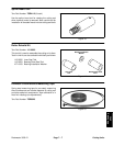
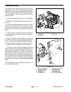
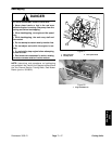
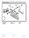
1. Reel motor location 2. Weight location
Figure 19
FRONT
3
4
5
1
2
1
2
2
1
1
2 11
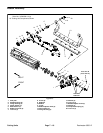
1. Hydraulic reel motor 2. Flange nut or flange
head screw (2)
Figure 20
2
1
2. Coat spline shaft of the reel motor with No. 2 multi-
purpose lithium base grease. Lubricate the O−ring on
the motor flange with clean oil.
3. Rotate the motor clockwise so the motor flanges
clear the flange nuts in the cutting unit side plates. Align
reel motor shaft splines with cutting reel insert splines.
Slide motor shaft into reel insert.
4. Rotate the motor counter−clockwise until the motor
flanges are encircling the cap screws in the side plates.
While holding motor, tighten two (2) flange nuts or flange
head screws to secure reel motor to cutting unit
(Fig. 20).
DPA Cutting
Units