


Reelmaster 3550−D
Cutting Units
Page 7 − 28
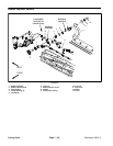
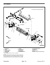
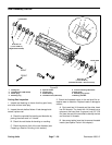
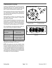
Reel Assembly Service
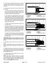
1. Cutting reel
2. Threaded insert (RH thread)
3. Plastic plug
4. Retaining ring
5. Special washer
6. Flocked seal
7. Sealed bearing
8. Threaded insert (LH thread)
9. Groove indicating LH threads
10. Reel spider
11. Retaining ring groove
12. Bearing shoulder
Figure 35
85 to 95 ft−lb
(115 to 128 N−m)
85 to 95 ft−lb
(115 to 128 N−m)
Loctite #242
Loctite #242
11
9
12
10
FRONT
RIGHT
(Right Hand Threads)
(Left Hand Threads − Groove in Face)
10
1
2
7
3
3
4
4
5
6
5
6
7
8
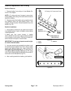
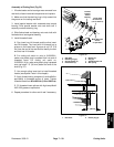
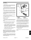
Cutting Reel Inspection
1. Inspect reel bearings to insure that they spin freely
and have minimal axial play.
2. Inspect the reel shaft as follows. If reel damage is de-
tected, replace reel.
A. Check the reel shaft for bending and distortion by
placing the shaft ends in V−blocks.
B. Check the reel blades for bending or cracking.
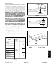
C. Check the service limit of the reel diameter (see
Preparing a Reel for Grinding in this section).
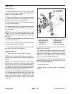
3. Check the threaded inserts in the reel shaft for ex-
cessive wear or distortion. Replace inserts if damage is
evident.
A. One insert has LH threads and the other insert
has RH threads. The insert with LH threads has a
groove on the insert face. A groove is cut 2.2” (5.6
cm) from the end of the reel shaft to identify the reel
end that has LH threads.
B. Use correct spline insert tool to remove threaded
inserts (see Special Tools in this chapter).