


Reelmaster 3550−DHydraulic System Page 4 − 96
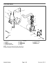
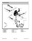
Cutting Unit Reel Motor Service
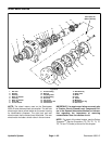
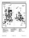
1. Dust seal
2. Retaining ring
3. Backup washer
4. Shaft seal
5. Front flange
6. Dowel pin (2)
7. O–ring
8. Pressure seal (outer)
9. Backup gasket (outer)
10. Wear plate (outer)
11. Drive gear
12. Idler gear
13. Wear plate (inner)
14. Backup gasket (inner)
15. Pressure seal (inner)
16. Body
17. Cap screw (4)
18. Washer (4)
Figure 61
1
3
4
5
6
7
9
11
10
8
14
13
2
12
17
18
(25 N−m)
18 ft−lb
15
16
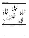
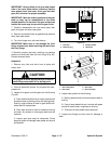
Disassembly (Fig. 61)
1. Plug motor ports and clean the outside of the motor
thoroughly. After cleaning, remove plugs and drain any
fluid out of the motor.
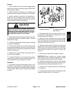
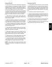
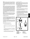
2. Use a marker to make a diagonal line across the
front flange and body for assembly purposes (Fig. 62).
IMPORTANT: Prevent damage when clamping the
motor into a vise; use a vise with soft jaws and
clamp on the front flange only.
3. Clamp front flange of motor in a vise with soft jaws
with the shaft end down.
4. Loosen cap screws from the rear cover.
5. Remove motor from the vise. Turn motor so that the
shaft end is facing down and remove cap screws.
Figure 62
MARKER
LINE
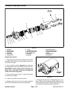
6. Carefully remove body. Lift body straight up to re-
move. Make sure the rear wear plate remains on the
drive and idler gear shafts. Remove and discard O–ring
from the body. Locate and retrieve dowel pins.