


Reelmaster 3550−DPage 5 − 6Electrical System
Troubleshooting
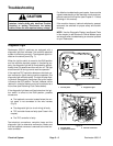
CAUTION
Remove all jewelry, especially rings and
watches, before doing any electrical trouble-
shooting or testing. Disconnect the battery
cables unless the test requires battery voltage.
For effective troubleshooting and repairs, there must be
a good understanding of the electrical circuits and com-
ponents used on this machine (see Chapter 8 − Foldout
Drawings in this manual).
If the machine has any interlock switches by−passed,
reconnect the switches for proper safety and trouble-
shooting.
NOTE: Use the Diagnostic Display (see Special Tools
in this chapter) to test Electronic Control Module inputs
and outputs when troubleshooting an electrical problem
on your Reelmaster.
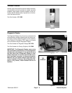
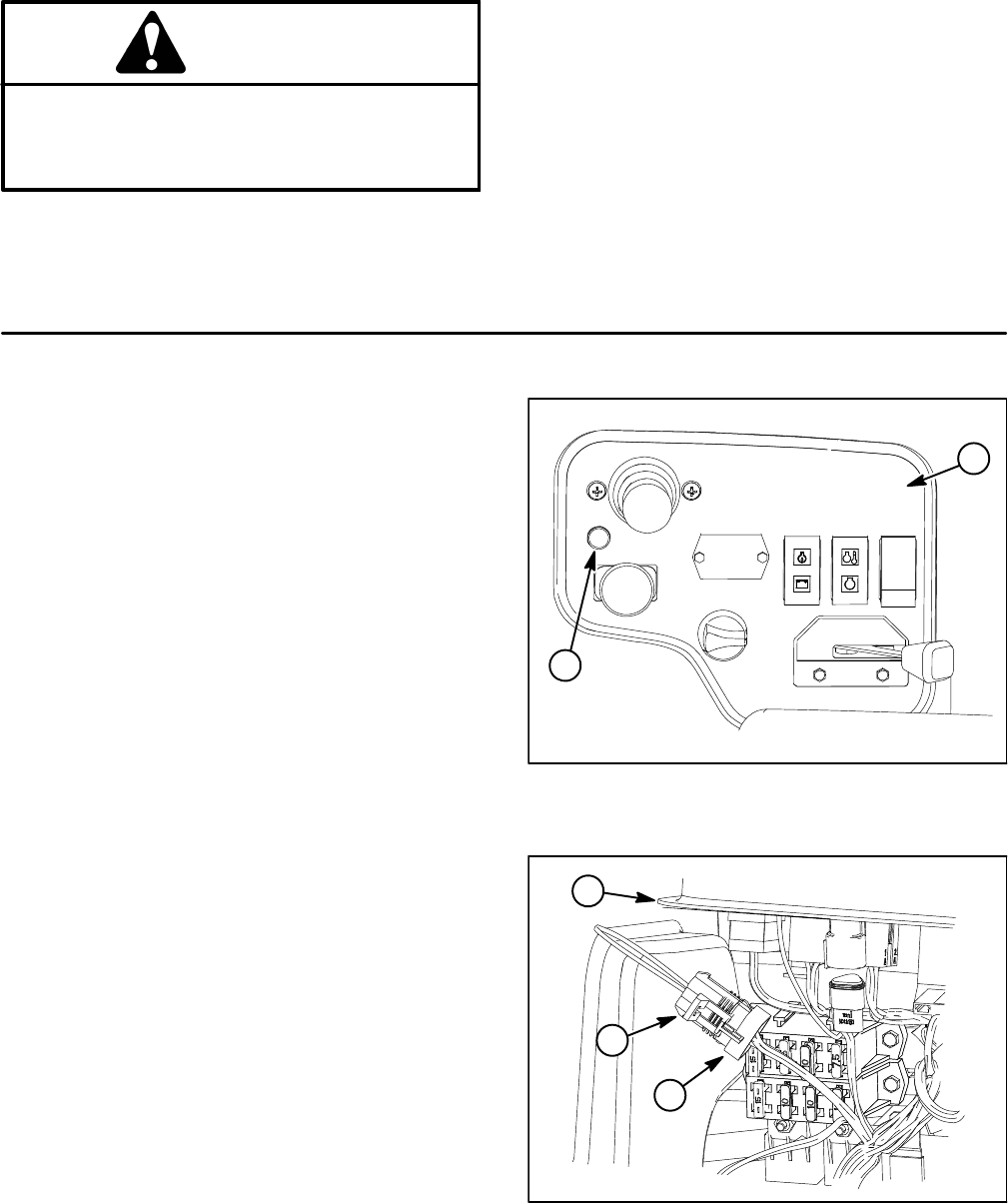
Diagnostic Light
Reelmaster 3550−D machines are equipped with a
diagnostic light that indicates if the machine electrical
system is functioning correctly. The diagnostic light is lo-
cated on the control panel (Fig. 7).
When the ignition switch is moved to the RUN position
and the machine electrical system is functioning pro-
perly, the diagnostic light will be illuminated for approxi-
mately three (3) seconds and then will turn off. The light
should remain off during normal machine operation.
If the machine TEC controller detects an electrical sys-
tem malfunction (fault) during machine operation, the
diagnostic light will flash rapidly. The light will stop flash-
ing and will automatically reset when the ignition switch
is turned to the OFF position. The fault, however, will be
retained in controller memory and can be retrieved at a
future time (see Retrieving Fault Codes below).
If the diagnostic light does not illuminate when the igni-
tion switch is turned to the RUN position, possible
causes are:
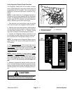
D The loopback connector located below the con-
trol panel is not connected to the wire harness
(Fig. 8).
D The diagnostic light (or circuit wiring) is faulty.
D TEC controller fuses are faulty (see Fuses in this
chapter).
D The TEC controller is faulty.
Test electrical connections, controller fuses and the
diagnostic light to determine malfunction. Make sure
that the loopback connector is secured to the wire har-
ness connector.
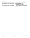
1. Control panel 2. Diagnostic light
Figure 7
2
1
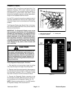
Figure 8
1. Control panel
2. Loopback connector
3. Harness connector
1
2
3