


Reelmaster 3550−D
Cutting Units
Page 7 − 26
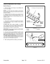
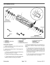
7. Remove cap screw and flat washer that secure rear
grass shield to LH side plate.
8. Remove flange head screw and flange nut that se-
cures frame spacer and carrier frame to LH side plate.
NOTE: The reel bearings and grease seals are press fit
on the cutting reel shaft and should remain on the reel
when removing the LH side plate.
9. Remove two (2) shoulder bolts and flange nuts that
secure the LH side plate to the cutting unit frame. Re-
move the LH side plate from the reel shaft and cutting
unit frame.
CAUTION
Contact with the reel, bedknife or other cutting
unit parts can result in personal injury. Use
heavy gloves when removing the cutting reel.
10.Carefully slide the cutting reel assembly from the RH
side plate.
11.Inspect and service cutting reel assembly as re-
quired (see Reel Assembly Service in this chapter).
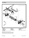
Installation (Fig. 32 & 33)
1. Thoroughly clean side plates and other cutting unit
components. Inspect side plates for wear or damage
and replace if needed.
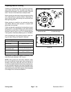
2. Make sure that grease seals and bearings are prop-
erly installed on cutting reel (see Reel Assembly Service
in this Chapter).
3. Cutting unit serial nos. 315000001 & Up have
O−rings in the reel bearing bore of each side plate. Make
sure the O−rings are in good condition and properly in-
stalled in the side plates.
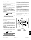
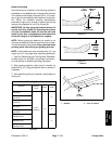
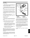
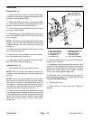
4. Apply a thin coat of antiseize lubricant to the reel
bearing bore of each side plate (Fig. 34).
CAUTION
Contact with the reel, bedknife or other cutting
unit parts can result in personal injury. Use
heavy gloves when installing the cutting reel.
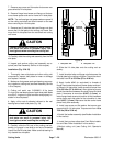
5. Carefully slide the RH end of the cutting reel as-
sembly (no groove in reel shaft or on face of threaded
insert) into the RH side plate. Make sure that bearing is
fully seated into side plate.
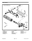
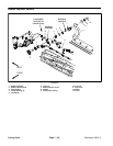
1. Side plate − RH 2. Side plate − LH
Figure 34
12
Antiseize
Lubricant
6. Slide the LH side plate onto the cutting reel as-
sembly.
7. Install shoulder bolts and flange nuts that secure the
LH side plate to the cutting unit frame. Torque the shoul-
der bolts from 27 to 33 ft-lbs (37 to 44 N−m).
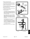
8. Apply Loctite #242 (or equivalent) to threads of
flange head screw that secures frame spacer and carri-
er frame to LH side plate. Install screw and torque from
27 to 33 ft-lbs (37 to 44 N−m). After tightening screw,
check the clearance between the carrier frame and side
plate. If clearance is more than 0.065” (1.6 mm), re-
move flange head screw and position shim(s) between
carrier frame and side plate so that clearance is less
than 0.065” (1.6 mm). Make sure that the carrier frame
pivots freely after assembly.
9. Install cap screw and flat washer that secure rear
grass shield to LH side plate. Torque screw from 15 to
19 ft-lbs (20 to 25 N−m).
10.Install the bedbar assembly (see Bedbar Installation
in this section).
11.Install front and rear rollers (see Front Roller Installa-
tion and Rear Roller Installation in this section).
12.Adjust cutting unit (see Cutting Unit Operator’s
Manual).