


Reelmaster 3550−D Hydraulic SystemPage 4 − 121
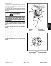
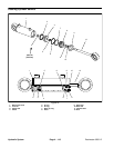
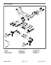
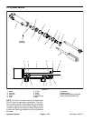
Removal (Fig. 77)
1. Park machine on a level surface. Lower cutting units,
stop engine and engage parking brake. Remove key
from the ignition switch.
2. Read the General Precautions for Removing and
Installing Hydraulic System Components in this chapter.
3. To prevent contamination of hydraulic system during
lift cylinder removal, thoroughly clean exterior of cylin-
der and fittings.
WARNING
Make sure that the cutting units are fully lowered
before loosening hydraulic lines from lift cylin-
ders. If cutting units are not fully lowered as hy-
draulic lines are loosened, cutting units may
drop unexpectedly.
NOTE: To ease installation, label the hydraulic hoses to
show their correct position on the lift cylinder.
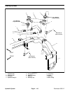
4. Disconnect hydraulic hoses from lift cylinder being
removed and plug hydraulic hoses to prevent contami-
nation.
5. Remove retaining ring and flat washer from one end
of the cylinder pin that secures rod end of lift cylinder to
lift arm. Pull pin from lift arm and cylinder rod.
6. Remove pin from frame and cylinder barrel clevis.
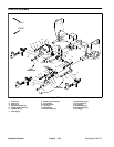
A. For outer lift cylinders, remove washer head
screw that secures the pivot pin to the frame. Slide
pivot pin from frame and cylinder barrel clevis.
B. For inner lift cylinder, remove lynch pin and thrust
washer that retains pin in frame. Slide pin from frame
and cylinder barrel clevis.
7. Remove lift cylinder from machine.
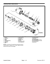
8. If hydraulic fittings are to be removed from lift cylind-
er, mark fitting orientation to allow correct assembly. Re-
move fittings from cylinder and discard O−rings.
Installation (Fig. 77)
1. If fittings were removed from lift cylinder, lubricate
and place new O−rings onto fittings. Install fittings into
cylinder port openings using marks made during the re-
moval process to properly orientate fittings. Tighten fit-
tings (see Hydraulic Fitting Installation in this chapter).
2. Secure cylinder barrel clevis to frame.
A. Slide pivot pin into frame and cylinder barrel cle-
vis. Secure pivot pin to frame with washer head
screw.
B. For inner lift cylinder, make sure that roll pin is in
good condition and is installed in pin. Slide pin into
frame and cylinder barrel clevis. Secure pin to frame
with thrust washer and lynch pin.
3. Make sure that flat washer and retaining ring are in-
stalled on one end of the cylinder pin.
4. Position cylinder rod end to lift arm and insert pin
through lift arm and cylinder rod end. Secure pin to lift
arm with second flat washer and retaining ring.
5. Attach hydraulic hoses to lift cylinder (see Hydraulic
Hose and Tube Installation in this chapter).
6. Fill reservoir with hydraulic fluid as required.
7. After installation is completed, operate lift cylinder to
verify that lift cylinder, hydraulic hoses and fittings are
not contacted by anything.
Hydraulic
System