


Reelmaster 3550−DPage 5 − 32Electrical System
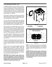
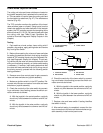
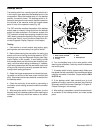
Backlap Switch
The backlap switch is a normally open ball switch that is
in the normal, open state when the backlap lever is in the
mow position. When the backlap lever is in the backlap
position, the switch closes. The backlap switch is at-
tached to the hydraulic mow control manifold located on
the left side of the machine under the hinged access
panel in front of the operator’s seat (Fig. 34).
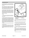
The TEC controller monitors the position of the backlap
switch (open or closed). Using inputs from the backlap
switch and other switches in the interlock system, the
TEC controller controls the energizing of solenoid valve
(MV) used to reverse the direction of the cutting unit reel
motors (see Table 3: Input Conditions Required to Illu-
minate Diagnostic Display Outputs in this chapter).
Testing
1. Park vehicle on a level surface, stop engine, apply
parking brake and remove key from ignition switch.
2. Before disconnecting the seat switch for testing, the
switch and its circuit wiring should be tested as a TEC
electrical input using the Diagnostic Display (see Diag-
nostic Display in this chapter). If input testing verifies
that the seat switch and circuit wiring are functioning cor-
rectly, no further switch testing is necessary. If, however,
input testing determines that the seat switch and circuit
wiring are not functioning correctly, proceed with the fol-
lowing switch testing procedure.
3. Raise the hinged access panel and locate the back-
lap switch on the front of the mow control manifold (left
side). Disconnect the harness electrical connector from
the backlap switch.
4. Check the continuity of the switch by connecting a
multimeter (ohms setting) across the switch connector
terminals.
5. With the ignition switch in the OFF position, turn the
backlap lever to the backlap position while watching the
multimeter. Continuity should be made as the switch
closes.
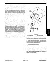
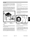
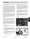
1. Mow control manifold
2. Backlap switch
3. O−ring
4. Ball
5. Backlap lever
Figure 34
1
5
2
3
4
20 ft−lb (27 N−m)
6. Turn the backlap lever to the mow position while
watching the multimeter. Continuity should be broken as
the switch opens.
7. If backlap switch is faulty, replace switch. Make sure
that dowel and ball are placed in the manifold port before
installing new switch in manifold. Torque switch to 20 ft-
lb (27 N- m).
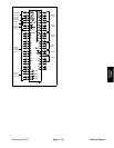
8. If the backlap switch tests correctly and a circuit
problem still exists, check wire harness (see Electrical
Schematic and Wire Harness Drawings in Chapter 9 -
Foldout Drawings in this manual).
9. After testing is completed, connect harness electric-
al connector to the backlap switch and close access
panel.