


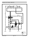

Reelmaster 3550−D Hydraulic SystemPage 4 − 51
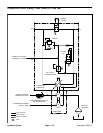
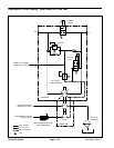
Cutting Unit Circuit Testing − Mow Control Manifold
Relief Valve (RV) Pressure Test:
If a rear cutting unit suddenly becomes obstructed dur-
ing operation, mow control manifold relief valve (RV)
protects the obstructed cutting unit from additional dam-
age by diverting the oil flow from the front cutting units.
Test the performance of the mow control manifold relief
valve (RV) to make sure that the relief valve opens at the
specified pressure.
Special Equipment Required:
S Flow Meter with Pressure Gauge that has at least
a 12 GPM (45 LPM) capacity.
S Phototach (non−contact tachometer).
1. Park machine on a level surface with the cutting units
lowered, reel engage/disengage switch in the disen-
gage position, and the mow/transport switch in the
MOW position. Engine should be off and the parking
brake disengaged.
2. Read Precautions for Hydraulic Testing in this
chapter.
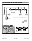
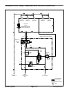
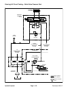
3. Disconnect the inlet hose for the rear left (cutting unit
#2) reel motor at the frame bulkhead fitting (Fig. 34).
4. Install tester between the disconnected hydraulic
hose and the bulkhead fitting. Make sure the tester flow
direction is from the bulkhead fitting toward the reel mo-
tor, and that the tester flow control valve is fully open.
5. Make sure backlap knob on the hydraulic manifold is
in the MOW position, and the reel speed knob is set to
maximum.
6. Start the engine, and move throttle to full speed
(3220 +
50 RPM).
7. Make sure hydraulic fluid is at normal operating tem-
perature by operating the machine for approximately 10
minutes.
8. Verify with a phototach that the pump speed is ap-
proximately 3090 RPM.
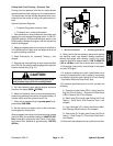
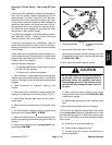
CAUTION
Keep away from reels during test to prevent per-
sonal injury from the rotating reel blades.
9. Engage cutting units.
10.Watch pressure gauge carefully while slowly closing
the flow control valve.
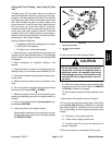
#2 #3
#1#4 #5
1. Reel motor #2
inlet hose
2. Frame bulkhead fitting
Figure 34
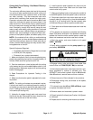
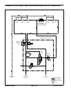
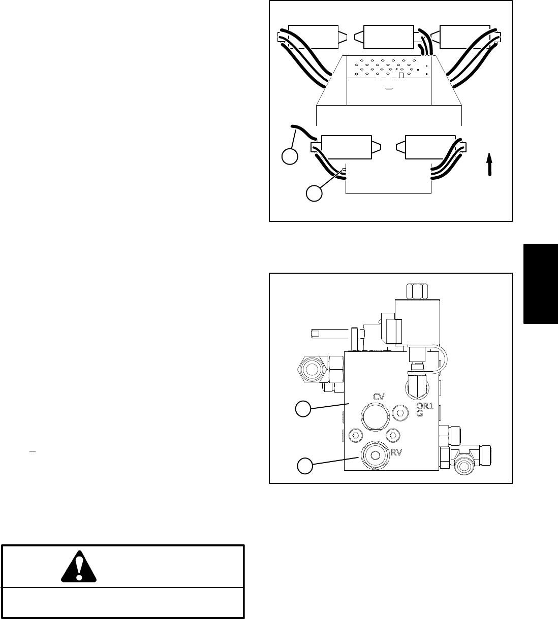
1
FRONT
2
1. Mow control manifold 2. Relief valve (RV)
Figure 35
1
2
11.System pressure should reach 1500 PSI (103.4 Bar)
before the relief valve opens.
12.Set throttle to low speed and shut off engine.
13.If specification is met, test pump (P1) flow (see Cut-
ting Unit Circuit Testing − Gear Pump (P1) Flow Test in
this chapter) If specification is not met, adjust relief valve
(RV) (see Adjustments in this chapter) and retest. If spe-
cification is still not met, clean or replace relief valve
(RV) (see Hydraulic Manifold Service in this chapter)
and retest.
14.Disconnect tester and reconnect hydraulic hoses.
Hydraulic
System