


Reelmaster 3550−D Page 6 − 19 Chassis
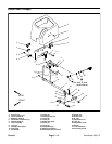
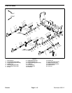
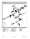
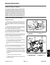
Removal (Fig. 12)
1. Park machine on a level surface, lower cutting units,
stop engine, engage parking brake, and remove key
from the ignition switch.
2. Remove cutting units (see Chapter 7 − Cutting Units
in this manual).
3. Remove lynch pin and thrust washer securing pivot
yoke to lift arm and remove pivot yoke.
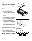
4. Remove retaining ring and flat washer from one end
of the cylinder pin that secures rod end of lift cylinder to
lift arm. Pull pin from lift arm and cylinder rod. Support
lift cylinder away from lift arm. DO NOT allow the lift cyl-
inder to hang by the hydraulic hoses.
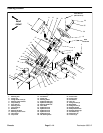
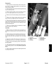
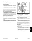
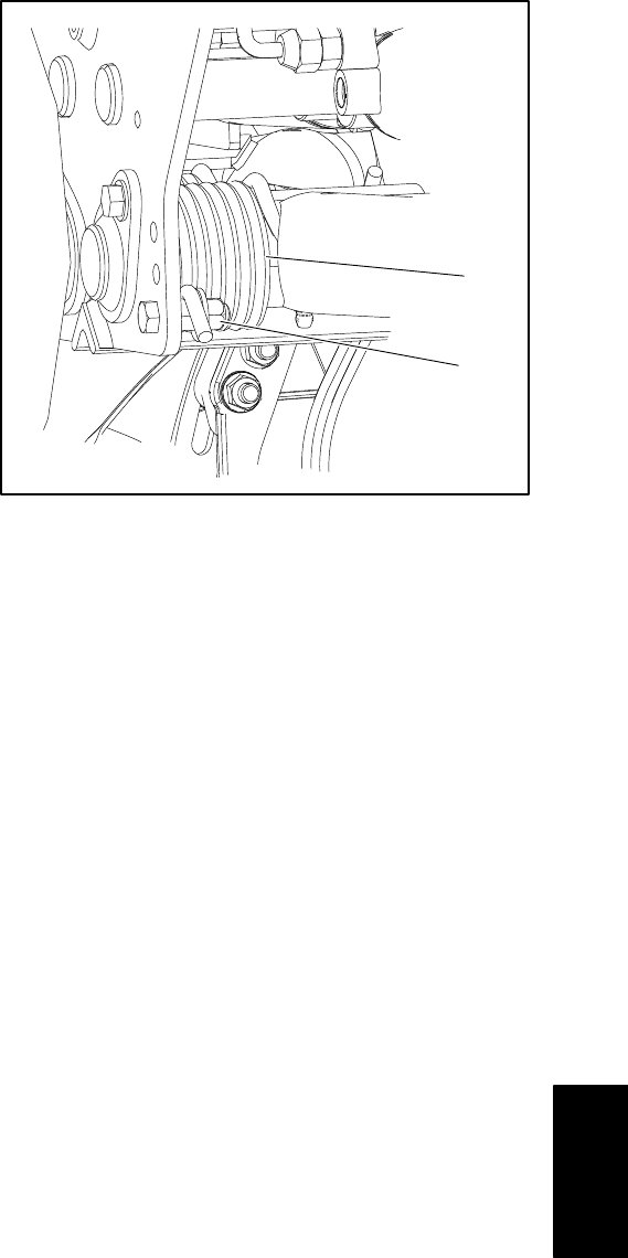
5. Note the position of the spring actuator prior to re-
moval for proper assembly. Insert a tube or similar object
onto the straight end of the counterbalance spring. Lift
the spring end up and remove the spring actuator (cap
screw, spacer, washer, and lock nut) (Fig. 13). Relieve
all tension from the counterbalance spring.
6. Remove flange head screw from lift arm pin.
7. Support lift arm assembly and slide lift arm pin from
frame. Remove lift arm assembly and counterbalance
spring.
8. Remove hex head screw and drive lift arm pin from
frame if necessary.
9. Repair lift arm as necessary.
1. Counterbalance spring 2. Spring actuator
Figure 13
1
2
Installation (Fig. 12)
1. If the lift arm pin was removed from frame, install lift
arm pin in frame and secure with cap screw.
2. Position counterbalance spring over lift arm as
shown.
3. Support lift arm and slide lift arm pin into frame. Se-
cure lift arm pin to frame with flange head screw.
4. Insert a tube or similar object onto the straight end of
the counterbalance spring. Lift the spring end up and in-
stall the spring actuator (cap screw, spacer, washer, and
lock nut) (Fig. 13). Rest end of counterbalance spring on
spring actuator.
5. Slide pivot yoke into lift arm and secure with thrust
washer and lynch pin.
6. Secure hydraulic cylinder to the lift arm with pins,
washers, and retaining rings.
7. Install cutting unit to the rear lift arm pivot yoke (see
Chapter 7 − Cutting Units in this manual).
8. Grease rear lift arm and pivot yoke.
Chassis