


Reelmaster 3550−DGroomer Page 8 − 6
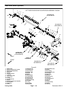
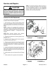
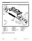
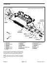
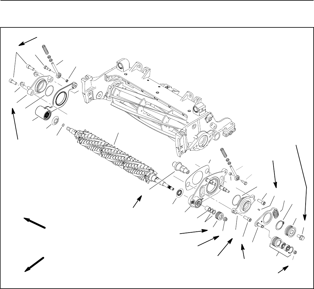
Groomer Plate Assembly
Figure 3
1. Groomer reel
2. Pulley spacer
3. Washer (as required)
4. Square key
5. Driven pulley
6. Flange nut
7. Socket head screw (4)
8. Idler plate
9. Idler pulley assembly
10. Lock nut
11. Flange head screw
12. Drive pulley
13. Retaining ring
14. Extension spring
15. Pivot hub (drive)
16. O−ring
17. Groomer plate assembly (drive)
18. Groomer shim
19. Shoulder bolt (2)
20. Pivot hub assembly (non−drive)
21. Flange nut (2)
22. Groomer plate assembly
(non−drive)
23. Excluder seal (2)
24. O−ring
25. Ball joint rod (2)
26. Spacer (2)
27. Drive shaft
27 to 33 ft−lb
(37 to 44 N−m)
FRONT
RIGHT
Antiseize
Lubricant
Antiseize
Lubricant
27 to 33 ft−lb
(37 to 44 N−m)
Loctite #242
Loctite #242
Loctite #242
Left Side Driven Groomer Assembly Shown
5
3
1
2
9
10
11
8
6
7
12
7
7
4
13
14
17
18
15
16
19
20
21
22
23
24
23
16
26
25
25
26
Antiseize
Lubricant
Antiseize
Lubricant
75 to 90 in−lb
(8 to 10 N−m)
19
27
Loctite #242
85 to 98 ft−lb
(115 to 129 N−m)
NOTE: The groomer reel drive is located on the oppos-
ite side of the cutting unit from the cutting unit hydraulic
motor.