


Reelmaster 3550−D Hydraulic SystemPage 4 − 17
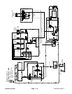
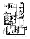
Traction Circuit
The traction circuit of the hydraulic system consists of a
hydrostat connected in a closed loop circuit to three or-
bital geroller wheel motors.
The mow/transport slide control on Reelmaster 3550−D
machines has positions for mow and transport. The
mow position allows traction pedal inputs that are appro-
priate for mow speeds by limiting the movement of the
traction pedal and the piston pump swash plate. The
transport position allows full movement of the traction
pedal so complete pump swash rotation is possible.
Forward
The engine drives traction pump (P3) indirectly through
pulleys and a V−belt. The traction pump is a variable dis-
placement piston pump/hydrostat. The traction pedal
connects through a cable to the trunnion shaft and
swash plate of the pump. With the engine running and
the traction pedal in the neutral position, traction pump
(P3) supplies no flow to the wheel motors. When the
traction pedal is pressed to the forward position, the
cable from the pedal positions the swash plate in the
traction pump so fluid flows out of the hydrostat lower
port. Fluid flow out of the lower port goes to the front
wheel motors first, turning them in the forward direction.
Fluid flowing out of the front wheel motors flows to the
rear wheel motor, turning it in a forward direction. Fluid
flowing out of the rear wheel motor returns to the upper
port of the hydrostat and is continuously pumped out of
the lower port.
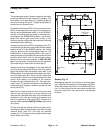
Operating pressure in the closed traction circuit is deter-
mined by the amount of load developed by the wheel
motors. As the load increases, circuit pressure can in-
crease to the relief valve setting of 3500 psi (241 bar).
In forward operation, fluid flows through the internal hy-
drostat relief valve to the low pressure side of the trac-
tion circuit when circuit pressure exceeds the relief
setting.
Reverse
The traction circuit operates essentially the same in re-
verse as it does in forward. However, there are a few dif-
ferences in operation.
When the reverse traction pedal is depressed, the cable
from the pedal positions the swash plate in the traction
pump (P3) so fluid flows out of the hydrostat upper port.
Fluid flow out of the upper port goes to the rear wheel
motor where an internal check valve allows the hydraul-
ic fluid to bypass the motor. Fluid flow out of the rear
wheel motor flows to the front wheel motors, turning
them in the reverse direction. Fluid flow out of the front
wheel motors returns to the lower port of the hydrostat
and is continuously pumped out of the upper port.
NOTE: The rear wheel motor does not help propel the
traction unit in reverse.
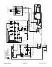
Charge Circuit
The traction pump uses a small amount of hydraulic fluid
for internal lubrication. Fluid is designed to leak across
internal pump parts into the case drain. This leakage re-
sults in the loss of hydraulic fluid from the closed loop cir-
cuit that must be replenished via the charge circuit.
The gear pump (P2) is directly coupled to the hydrostat
through gear pump (P1) and driven by the engine. Gear
pump (P2) supplies hydraulic pressure for operating the
power steering system, raising and lowering the cutting
units, and operating the sidewinder unit. Gear pump
(P2) may also be referred to as the charge pump as flow
from the gear pump also replenishes the closed loop
traction circuit. Hydraulic fluid exits the lift/sidewinder
valve, passes through the hydraulic manifold where it
actuates logic cartridge (LC1), and continues on to the
hydrostat. A relief valve located in the hydrostat
provides sufficient resistance so that flow is guided to
the low pressure side of the traction circuit through one
of two check valves (charge circuit). Pump flow in ex-
cess of charge circuit requirements is relieved through
the relief valve back to the gear pump inlet and hydraulic
tank.
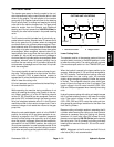
Traction Circuit Cooling
The traction circuit is cooled by a bleed off circuit in the
piston pump. The piston pump includes an internal
bleed valve which allows a small amount of hydraulic oil
to pass from the return side of the pump while operating
the traction unit in the forward direction. The charge cir-
cuit replenishes oil that is bled from the traction circuit by
the bleed valve.
When operating the traction circuit in the reverse direc-
tion, the bleed valve closes once reverse pressure
reaches 200 to 300 PSI (13.8 to 20.6) to allow normal
reverse operation.
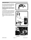
NOTE: The bleed valve threads into the piston pump
back plate. Access to the bleed valve requires removal
of the back plate from the piston pump.
Hydraulic
System