


Reelmaster 3550−D Hydraulic SystemPage 4 − 103
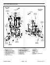
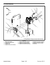
NOTE: The ports on the mow control manifold are
marked for easy identification of components. Example:
PRV is the proportional relief valve and T is the return
port (see Hydraulic Schematic to identify the function of
the hydraulic lines and cartridge valves at each port
location).
NOTE: The hydraulic manifold shown uses several
zero leak plugs. These plugs have a tapered sealing
surface on the plug head that is designed to resist vibra-
tion induced plug loosening. The zero leak plugs also
have an O−ring to provide a secondary seal. If zero leak
plug removal is necessary, lightly rap the plug head us-
ing a punch and hammer before using an allen wrench
to remove the plug: the impact will allow plug removal wi-
th less chance of damage to the socket head of the plug.
When installing plugs into the manifold, torque plugs to
the values shown.
NOTE: The mow control manifold includes two (2) ori-
fice fittings. The 0.020” orifice threads into manifold port
OR2 under a hex plug. The 0.050” orifice threads into
manifold port OR1 under the diagnostic test fitting.
Cartridge Valve Service
The mow control manifold includes an adjustable relief
valve (RV). Mow control manifold relief valve (RV)
should be set to 1500 PSI (103 Bar). Adjust the relief
valve to the recommended setting as necessary (see
Adjustments in this chapter).
For cartridge valve service procedures, see Cartridge
Valve Service in this chapter. When installing cartridge
valves into the manifold, torque cartridge valves to the
values shown.
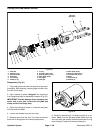
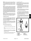
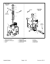
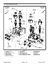
Rotary Handle Assembly (Fig. 67)
1. To remove rotary handle from valve:
A. Loosen two (2) set screws that secure handle
cap.
B. Remove screw and then lift handle cap from
valve.
C. Locate and retrieve detent pin, compression
spring, bushing and lip seal. The sleeve bearing
should stay in the cap.
D. Loosen two (2) set screws that secure handle
base to flow control valve and remove base.
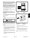
2. To install rotary handle:
IMPORTANT: Make sure that flow control cartridge
valve is properly secured in manifold before instal-
ling rotary handle to valve.
A. Place handle base on flow control valve and posi-
tion alignment mark on base with number 1 on man-
ifold. Secure base with two (2) set screws. Apply a
light coating of grease to chamfer on top of base to
ease seal installation.
B. Make sure that sleeve bearing is in handle cap. If
necessary, press sleeve bearing into cap. Install lip
seal on cap with seal lip facing down.
C. While pressing on the cap to keep the lip seal in
place, rotate cap in a clockwise direction until the ar-
row on the cap aligns with number 1 on the manifold.
By rotating the cap clockwise, the valve will remain
closed. Install screw to retain cap.
D. Make sure that alignment marks on cap and base
are in line and that arrow on cap is pointing to number
1 on manifold. Tighten two (2) set screws to secure
handle cap.
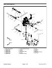
1. Handle base
2. Handle cap
3. Detent pin
4. Compression spring
5. Bushing
6. Set screw (2)
7. Set screw (2)
8. Screw
9. Lip seal
10. Sleeve bearing
11. Flow control valve
Figure 67
6
5
4
7
9
10
3
2
8
1
11
Hydraulic
System