


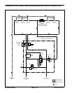
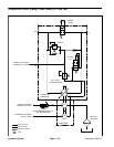
Reelmaster 3550−D Hydraulic SystemPage 4 − 45
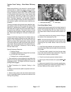
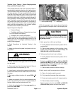
Cutting Unit Circuit Testing − Pressure Test:
Cutting unit circuit pressure is the first in a series of tests
recommended to check cutting unit circuit performance.
The results from this test will help determine which com-
ponent(s) are the cause of cutting unit performance is-
sues.
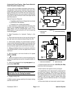
Special Equipment Required:
S Pressure Gauge with extension hose
S Phototach (non−contact tachometer).
1. Park machine on a level surface with the cutting units
lowered, the reel engage/disengage switch in the DIS-
ENGAGE position, and the mow/transport switch in the
MOW position. Make sure engine is off and the parking
brake is disengaged.
2. Make sure backlap knob on the hydraulic manifold is
in the MOW position. Make sure reel speed knob is set
for typical mowing conditions.
3. Read Precautions for Hydraulic Testing in this
chapter.
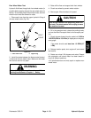
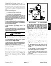
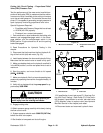
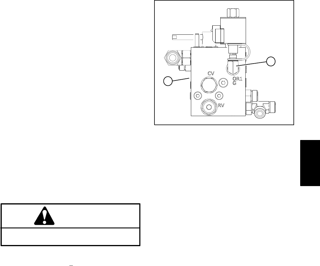
4. Remove cap from test fitting at mow control manifold
port (OR1/G) and install a pressure gauge with hydraulic
hose to the test fitting (Fig. 31).
CAUTION
Keep away from cutting units during test to pre-
vent personal injury from the cutting blades.
5. Sit in the Operator’s seat, start the engine, and move
throttle to full speed (3220 +
50 RPM).
6. Make sure hydraulic fluid is at normal operating tem-
perature by operating the machine for approximately 10
minutes. Make sure the hydraulic tank is full.
7. Verify with a phototach that the pump speed is ap-
proximately 3090 RPM.
8. Set the cutting unit speed control to #9 (maximum)
and engage the cutting units.
When engaged, the cutting circuit pressure may exceed
manifold relief valve pressure setting of 3000 PSI (207
Bar) momentarily opening the relief valve. Circuit pres-
sure should then stabilize at approximately 1200 PSI
(83 Bar).
1. Mow control manifold 2. Test fitting (port OR1/G
)
Figure 31
1
2
9. Safely secure the test pressure gauge and operate
the machine under your specific mowing conditions.
Monitor test gauge while mowing. Cutting unit circuit
pressure should be approximately: 1500 to 2000 PSI
(103 to 138 Bar) under low to normal load conditions.
10.Disengage cutting units, move throttle to low speed
and shut off engine.
11.If pressure readings are within specifications and
cutting unit performance is still in question, test cutting
unit motors individually (see Cutting Unit Circuit Testing
− Reel Motor Efficiency/Case Drain Test).
12.If pressure specifications are not met, consider the
following:
A. Proportional relief valve (PRV) is faulty (see Cut-
ting Unit Circuit Testing − Proportional Relief Valve
(PRV) Pressure Test in this chapter).
B. Relief valve (RV) is faulty (see Cutting Unit Circuit
Testing − Relief Valve (RV) Pressure Test in this
chapter).
C. Logic Cartridge (LC) Is faulty (see Control Mani-
fold Cartridge Valve Service in this chapter).
D. Gear pump (P1) is faulty (see Cutting Unit Circuit
Testing − Gear Pump (P1) Flow Under Load Test in
this chapter).
13.Disconnect test equipment from hydraulic manifold.
Hydraulic
System