


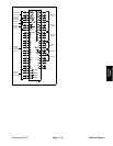
Reelmaster 3550−D Page 5 − 29 Electrical System
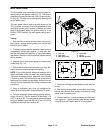
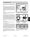
Reel Enable/Disable Switch
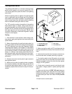
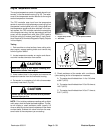
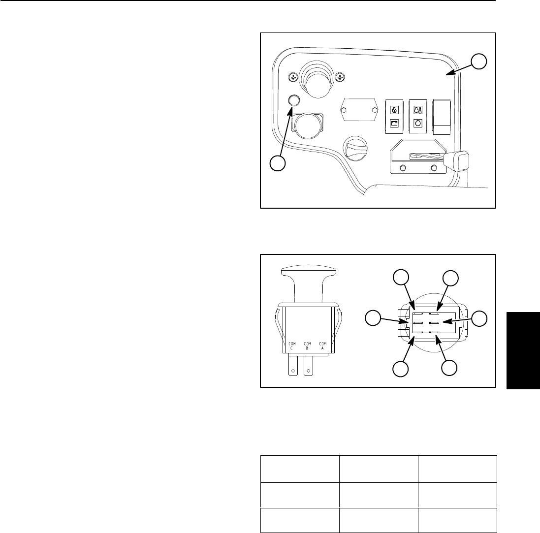
The enable/disable switch is located on the control
panel (Fig. 29). This switch is pulled out to engage the
cutting units and pushed in to disengage the cutting
units.
The TEC controller monitors the position of the enable/
disable switch (pulled out or pushed in). Using inputs
from the enable/disable switch and other switches in the
interlock system, the TEC controller controls the ener-
gizing of the proportional relief valve (PRV) used to drive
the cutting unit motors (see Table 3: Input Conditions
Required to Illuminate Diagnostic Display Outputs in
this chapter).
Testing
1. Park machine on level surface, lower cutting units,
stop engine, apply parking brake and remove key from
ignition switch.
2. Before disconnecting the enable/disable switch for
testing, the switch and its circuit wiring should be tested
as a TEC electrical input using the Diagnostic Display
(see Diagnostic Display in this chapter). If input testing
verifies that the enable/disable switch and circuit wiring
are functioning correctly, no further switch testing is nec-
essary. If, however, input testing determines that the en-
able/disable switch and circuit wiring are not functioning
correctly, proceed with the following switch testing pro-
cedure.
3. Remove cover from control panel to gain access to
enable/disable switch.
4. Disconnect wire harness electrical connector from
the enable/disable switch.
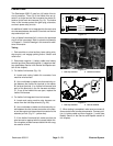
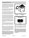
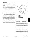
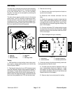
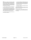
5. The enable/disable switch terminals are marked
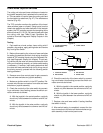
(Fig. 30). The circuit logic of the enable/disable switch
is shown in the chart (Fig. 31). With the use of a multime-
ter (ohms setting), the switch functions can be tested to
determine whether continuity exists between the vari-
ous terminals for each switch position. Verify continuity
between switch terminals. Replace enable/disable
switch if testing identifies that switch is faulty.
6. If the enable/disable switch tests correctly and circuit
problem still exists, check other circuit components (see
Electrical Schematic in Chapter 8 − Foldout Drawings in
this manual).
1. Control panel 2. Enable/disable switch
Figure 29
2
1
1. COM B terminal
2. NO B terminal
3. NC B terminal
4. COM C terminal
5. NO C terminal
6. NC C terminal
Figure 30
2
3
1
6
4
5
SWITCH
POSITION
CLOSED
CIRCUITS
OPEN
CIRCUITS
OFF (DOWN) COM B + NC B
COM C + NC C
COM B + NO B
COM C + NO C
ON (UP) COM B + NO B
COM C + NO C
COM B + NC B
COM C + NC C
Figure 31
7. After testing is completed, connect the wire harness
connector to the enable/disable switch. Install control
panel cover.
Electrical
System