


Reelmaster 3550−D Hydraulic SystemPage 4 − 21
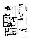
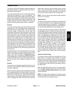
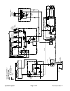
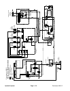
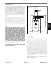
Lift Circuit: Lower
The tandem gear pump is directly coupled to the vari-
able displacement piston pump/hydrostat which is belt
driven by the engine. The rear section of the tandem
gear pump (P2) supplies hydraulic flow for the steering
circuit (priority flow), for raising and lowering the cutting
units and for the traction charge circuit. The gear pump
takes its suction from the hydraulic tank. Maximum
steering and lift circuit pressure of 1000 PSI (69 bar) is
limited by the relief valve located in the power steering
valve.
The lift control manifold includes four (4) electrically op-
erated solenoid valves. Solenoid valve S1 causes circuit
flow to by−pass the lift cylinders when de−energized
and directs flow to the cylinders when energized. Direc-
tional solenoid valve S2 is used to direct oil flow to raise
the cutting units when energized and lower them when
de−energized. When energized, solenoid valve S3 al-
lows hydraulic flow to and from the front cutting unit lift
cylinders (#1, #4 and #5) and prevents oil passage to
and from these lift cylinders when de−energized. When
energized, solenoid valve S4 allows hydraulic flow to
and from the rear cutting unit lift cylinders (#2 and #3)
and prevents oil passage to and from these lift cylinder
when de−energized.
The console joystick is used to raise and lower the cut-
ting units. The joystick acts as an input to the Toro Elec-
tronic Controller (TEC) to send electrical outputs to
appropriate lift control manifold solenoid coils in order to
raise or lower the cutting units.
Lift circuit pressure can be monitored at the test fitting in
lift control manifold port G1.
While operating the machine during conditions of not
raising or lowering the cutting units (joystick in the neu-
tral (center) position), all of the lift manifold solenoid
valves (S1, S2, S3 and S4) are de−energized. Flow from
gear pump (P2) is directed through the steering control
valve, de−energized solenoid valve S1 in the lift control
manifold and then to the traction charge circuit. Flow in
excess of charge circuit needs then returns to the gear
pump inlet.
When the reel enable/disable switch is in the ENABLE
position, the cutting unit lift and lower operation is con-
trolled by a program in the TEC controller (sequential
control) and the cutting units move fully up or fully down
when the joystick is bumped. When the reel enable/dis-
able switch is in the DISABLE position, the cutting unit
lift and lower operation is under complete control of the
joystick (momentary control) and the cutting units move
up or down only as long as the joystick is held in position.
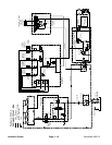
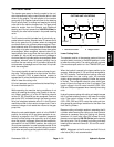
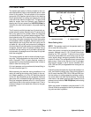
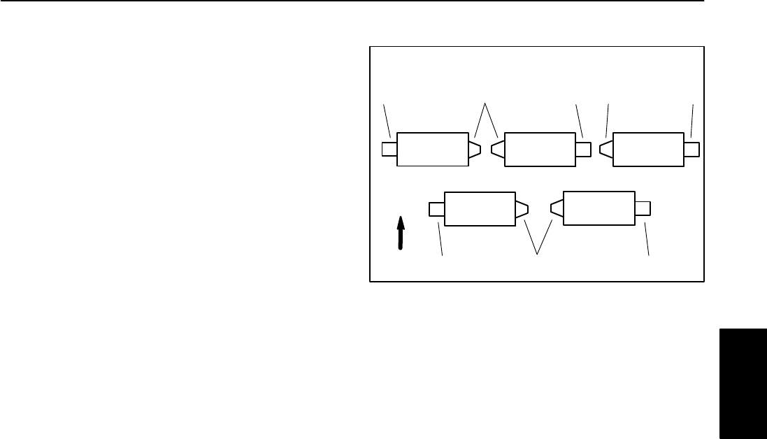
1. Reel motor location 2. Weight location
Figure 22
FRONT
#3
#4 #5
1
2
#1
#2
2
1
1
2 11
CUTTING UNIT LOCATIONS
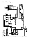
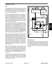
Lower Cutting Units
The operator must be in the operator seat and the mow/
transport switch must be in the MOW position in order
to lower the cutting units. The cutting units will not lower
if the mow/transport switch is in the TRANSPORT posi-
tion.
When the joystick is moved to the lower position by the
operator, solenoid valve S1, S3 and S4 are energized by
the TEC controller. To allow the front cutting units to be
lowered before the rear cutting units, the controller
slightly delays energizing solenoid S4 after the joystick
is moved. The energized solenoid valves direct gear
pump oil flow to the cap end of the lift cylinders. Flow
control orifices in the lift control manifold (OR2, OR4,
OR6 and OR8) are bypassed when lowering the cutting
units.
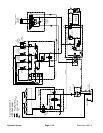
Hydraulic pressure along with cutting unit weight causes
the lift cylinder shafts to extend, and lower the cutting
units. Flow control orifices in the lift control manifold
(OR1, OR3, OR5 and OR7) control the cutting unit low-
ering speed by providing a restriction for the return flow
from the lift cylinders.
Because cutting unit weight assists in extending the lift
cylinders when lowering the cutting units, less hydraulic
pressure is necessary during the cutting unit lowering
operation. Lift circuit relief valve (RV) allows lift circuit
pressure to be limited to 500 PSI (34 bar) while lowering
the cutting units. The lift cylinders and cutting units stop
lowering when solenoid valves S1, S3 and S4 are de−
energized.
NOTE: Adjustment of the lift control manifold lift circuit
relief valve (RV) is not recommended.
Hydraulic
System