


Reelmaster 3550−DPage 5 − 20Electrical System
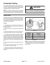
Component Testing
For accurate resistance and/or continuity checks, elec-
trically disconnect the component being tested from the
circuit (e.g. unplug the ignition switch connector before
checking continuity on the switch terminals).
NOTE: For engine component testing information
(starter solenoid and motor, alternator, glow plugs) see
the Kubota Workshop Manual: 05 Series Diesel Engine.
CAUTION
When testing electrical components for continu-
ity with a multimeter (ohms setting), make sure
that power to the circuit has been disconnected.
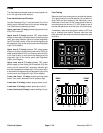
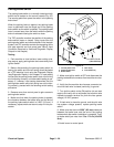
Ignition Switch
The ignition (key) switch is located on the control panel
and has three (3) positions: STOP, RUN and START
(Fig. 13). The Toro Electronic Controller (TEC) monitors
the operation of the ignition switch and reacts to the vari-
ous ignition switch positions.
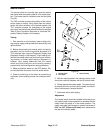
Testing
1. Park machine on a level surface, lower cutting units,
engage parking brake and stop engine. Remove key
from ignition switch.
2. Remove cover from control panel to access ignition
switch.
3. Make sure ignition switch is in the OFF position. Dis-
connect wire harness connector from ignition switch.
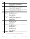
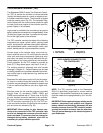
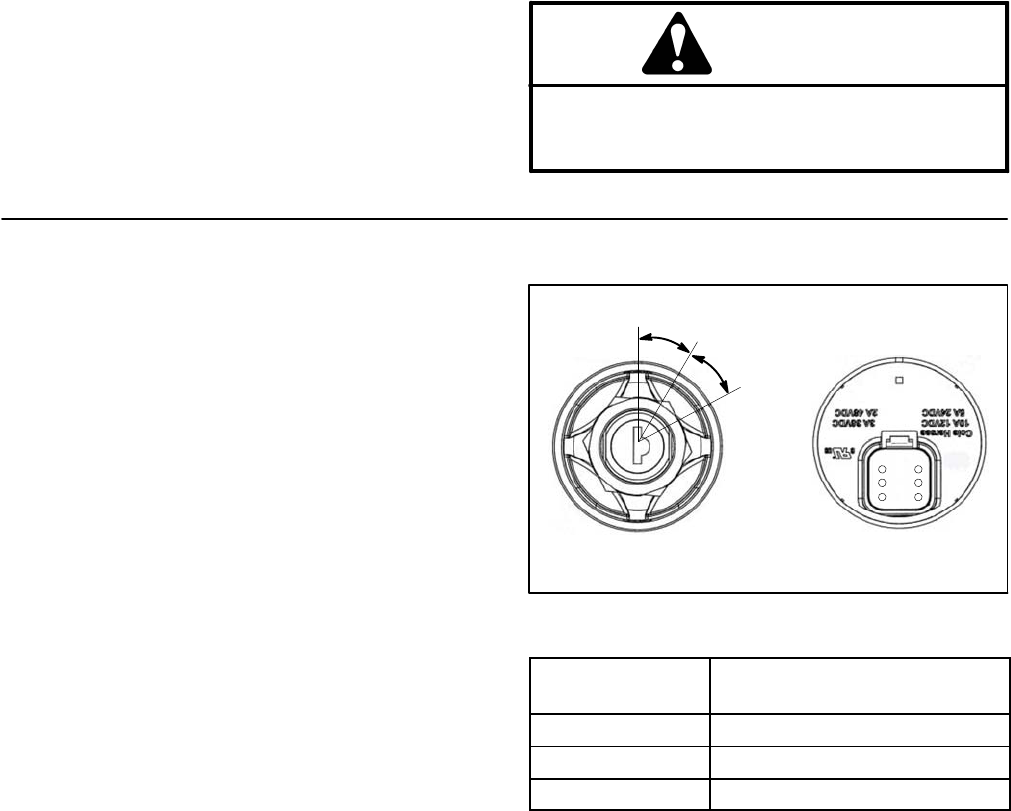
4. The ignition switch terminals are identified in Figure
13 and the circuitry of the switch is shown in the chart in
Figure 14. With the use of a multimeter (ohms setting),
the switch functions can be tested to determine whether
continuity exists between the various terminals for each
switch position. Verify continuity between switch termi-
nals.
5. Replace ignition switch if testing determines that it is
faulty.
6. If the ignition switch tests correctly and a circuit prob-
lem still exists, check wire harness.
7. After testing is complete, connect machine wire har-
ness connector to ignition switch. Install cover onto con-
trol panel.
Figure 13
REAR VIEW
FRONT VIEW
START
STOP
RUN
3
2
4
5
6
1
SWITCH
POSITION
CIRCUITS
STOP 1 + 6
RUN 1 + 3 + 4 + 5 + 6
START 1 + 2 + 4 + 5 + 6
Figure 14
NOTE: Ignition switch terminals 1 and 6 are connected
internally. Terminals 4 and 5 are also connected internal-
ly. These terminals should have continuity regardless of
switch position.