


Reelmaster 3550−D Page 5 − 37 Electrical System
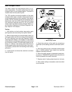
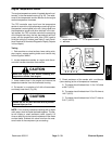
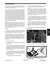
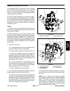
Fuel Stop Solenoid
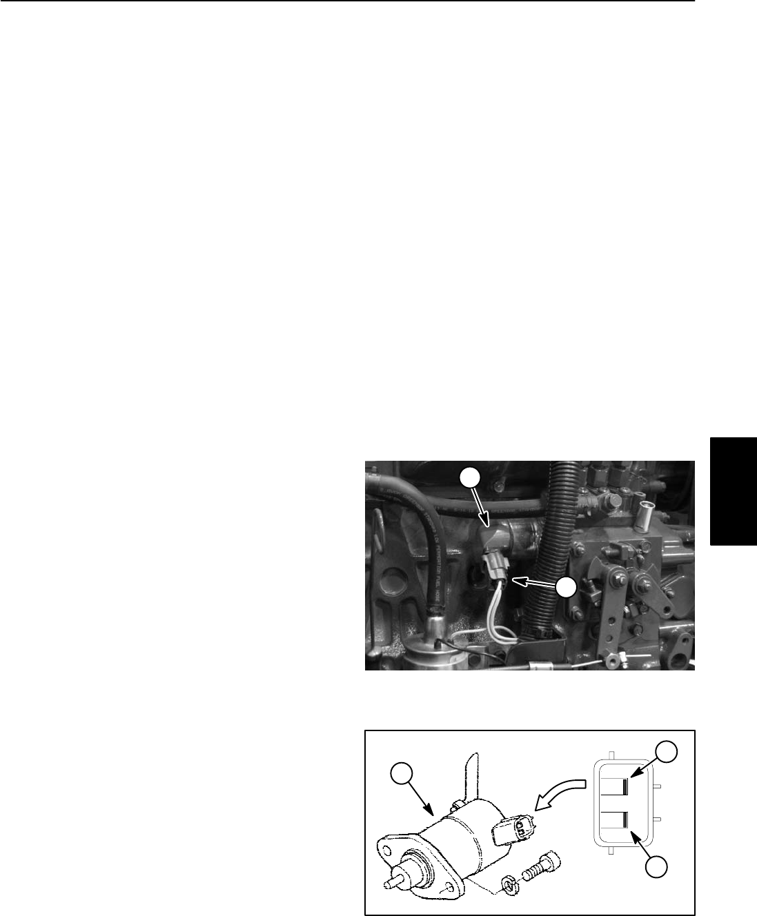
The fuel stop solenoid must be energized for the diesel
engine to run. The solenoid is mounted to the injection
pump on the engine (Fig. 39).
The fuel stop solenoid includes two coils for operation:
the pull coil and the hold coil. The TEC controller ener-
gizes and monitors the operation of the fuel stop solen-
oid when specific input conditions are met. When the
ignition switch is set to RUN or START, the fuel stop sole-
noid is energized and the pull coil retracts the solenoid
plunger. Once the plunger is retracted, the hold coil will
keep it retracted for continued engine operation. When
the solenoid is de−energized, the plunger extends to
shut off fuel supply to the engine causing the engine to
stop running. The fuel stop solenoid is grounded
through the solenoid housing.
NOTE: The TEC output circuit that controls the fuel
stop solenoid also controls the electric fuel pump. This
circuit is known as the Energize To Run (ETR) circuit.
Refer to the Electrical Schematics and Wire Harness
Drawings in Chapter 8 − Foldout Drawings in this manu-
al for additional information.
Testing
1. Park machine on a level surface, lower cutting units,
stop engine, engage parking brake and remove key
from the ignition switch. Unlatch and raise hood.
2. Test the ETR circuit as a TEC electrical output using
the Diagnostic Display (see Diagnostic Display in this
chapter). If output testing verifies that the TEC is ener-
gizing the ETR circuit under the appropriate conditions,
leave the diagnostic display connected and test the cir-
cuit wiring.
3. Test the circuit wiring:
A. Disconnect wire harness connector from the fuel
stop solenoid.
B. Position the necessary input(s) to illuminate the
ETR output LED indicating that the TEC controller is
energizing that function (see Table 3: Input Condi-
tions Required to Illuminate Diagnostic Display Out-
puts in this chapter).
C. Connect multimeter (DC voltage setting) across
the terminals of the wire harness connector. 12VDC
should be present at the connector when the ETR
LED is illuminated.
D. Repair damaged wiring as necessary.
4. If the circuit wiring is functioning correctly, use the fol-
lowing procedure to test the fuel stop solenoid.
NOTE: Prior to taking small resistance readings
with a digital multimeter, short the test leads togeth-
er. The meter will display a small resistance value
(usually 0.5 ohms or less). This resistance is due to
the internal resistance of the meter and test leads.
Subtract this value from the measured value of the
component you are testing.
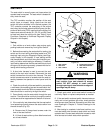
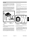
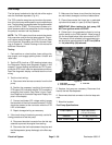
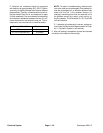
A. Using a digital multimeter, touch one test lead to
the pull coil terminal and the other test lead to the fuel
stop solenoid frame (ground) (Fig. 40). The resis-
tance of the pull coil should be less than 1 ohm (but
not zero).
B. Using a digital multimeter, touch one test lead to
the hold coil terminal and the other test lead to the
fuel stop solenoid frame (ground) (Fig. 40). The re-
sistance of the hold coil should be approximately 15
ohms.
5. Replace solenoid if necessary and reconnect the
wiring harness.
1. Fuel stop solenoid 2. Harness connector
Figure 39
2
1
1. Fuel stop solenoid
2. Pull coil terminal
3. Hold coil terminal
Figure 40
2
3
1
Electrical
System