


Reelmaster 3550−D Hydraulic SystemPage 4 − 41
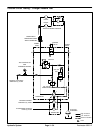
Traction Circuit Testing − Piston Pump/Hydrostat
Flow and Relief Pressure Test:
The hydrostat flow test is the third in a series of tests re-
commended to determine traction circuit performance.
The final traction circuit test is verifying the hydrostat re-
lief valve operation. This test compares fluid flow at No
Load with fluid flow Under Load. A drop in flow under
load of more than 12% indicates an internal leak or mal-
functioning relief valve in the piston pump/hydrostat. A
worn hydrostat or malfunctioning relief valve is less effi-
cient. Eventually, enough fluid by−pass will cause the
unit to stall under heavy load conditions. Continued op-
eration can generate excessive heat, cause damage to
seals and other components in the hydraulic system,
and affect overall machine performance.
Special Equipment Required:
S Pressure Gauge
S Flow Meter with Pressure Gauge that has at least
an 18 GPM (68 LPM) capacity.
S Phototach (non−contact tachometer).
1. Park machine on a level surface with the cutting units
lowered and the reel engage/disengage switch in the
disengage position. The engine should be off and the
parking brake engaged.
2. Read Precautions for Hydraulic Testing in this
chapter.
3. Make sure that traction pedal is adjusted to the neu-
tral position.
WARNING
Before jacking up the machine, review and follow
Jacking Instructions in Chapter 1 − Safety.
4. Raise off the floor and support both front wheels and
the rear wheel.
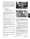
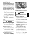
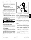
5. Disconnect hose from the lower hydraulic fitting on
the engine side of the hydrostat (Fig. 30).
6. Install tester in series with the pump and the discon-
nected hose. Make sure the tester flow control valve is
fully open.
7. Start engine. Move throttle to full speed (3220 + 50
RPM).
8. Make sure hydraulic fluid is at normal operating tem-
perature by operating the machine for approximately 10
minutes. Make sure the hydraulic tank is full.
9. Verify with a phototach that the pump speed is ap-
proximately 3090 RPM.
1. Lower hydraulic fitting 2. Piston pump
Figure 30
2
1
10.Sit in the operator’s seat, release the parking brake,
and set the Mow/Transport slide to the transport posi-
tion.
CAUTION
Use extreme caution when performing hydrostat
flow tests. The traction unit wheels will be rotat-
ing during the test.
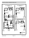
11.Verify pump flow at No Load as follows:
A. Slowly depress forward traction pedal to full for-
ward position.
B. Record tester pressure and flow readings. Unres-
tricted pump output should be approximately 18
GPM (69 LPM) at 650 PSI (44.8 Bar).
12. Verify pump flow Under Load as follows:
A. Slowly depress forward traction pedal to full for-
ward position.
B. Apply an additional load of 1000 to 1500 PSI
(68.9 to 103.4 Bar) by slowly closing the flow meter.
The flow meter pressure gauge should read 1700 to
2100 PSI (117.2 to 144.8 Bar).
C. Record tester pressure and flow readings.
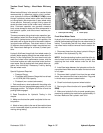
13.Verify traction relief valve operation as follows:
A. Return the traction pedal to neutral.
B. Fully close the flow meter flow control valve.
C. Slowly set traction pedal to full forward position.
D. Record tester pressure reading.
System pressure should reach 3600 to 3650 PSI
(248 to 251 Bar) before the relief valve opens.
Hydraulic
System